Operation – Nexen DPB-09T 960003 User Manual
Page 8
8
FORM NO. L-20094-D-0210
OPERATION
TABLE 2
Recommended Tightening Torques
N
O
I
T
P
I
R
C
S
E
D
T
9
-
B
P
D
T
1
1
-
B
P
D
T
3
1
-
B
P
D
T
5
1
-
B
P
D
)
3
1
m
e
tI
(
S
W
E
R
C
S
R
E
D
L
U
O
H
S
.
s
b
l.
tf
9
.
s
b
l.
tf
9
.
s
b
l.
tf
9
.
s
b
l.
tf
9
)
0
2
m
e
tI
(
T
U
N
K
C
O
L
.
s
b
l.
tf
2
3
.
s
b
l.
tf
0
7
.
s
b
l.
tf
0
7
.
s
b
l.
tf
0
7
)
1
2
m
e
tI
(
W
E
R
C
S
P
A
C
.
s
b
l.
tf
8
4
.
s
b
l.
tf
8
4
.
s
b
l.
tf
9
1
1
.
s
b
l.
tf
9
1
1
)
2
4
m
e
tI
(
W
E
R
C
S
P
A
C
.
s
b
l.
tf
9
1
1
.
s
b
l.
tf
9
1
1
.
s
b
l.
tf
9
1
1
.
s
b
l.
tf
9
1
1
)
4
4
m
e
tI
(
T
U
N
K
C
O
L
.
s
b
l.
tf
0
7
.
s
b
l.
tf
0
7
.
s
b
l.
tf
9
2
1
.
s
b
l.
tf
9
2
1
)
5
4
m
e
tI
(
T
U
N
K
C
O
L
.
s
b
l.
tf
0
0
2
.
s
b
l.
tf
0
0
2
.
s
b
l.
tf
0
0
2
.
s
b
l.
tf
0
0
2
The DPB Brake engages when air pressure is introduced into
the Cylinder/Drive Disc. Air pressure pushes the Cylinder/
Drive Disc against the Flange/Mount Disc, and forces the
Cylinder/Drive Disc in the opposite direction.
This engages the Friction Facings with the friction surfaces
of the Flange Mount Disc and Friction Disc.
Torque is transmitted through the Cylinder/Drive Disc
and Piston/Drive Disc to the Splined Hub attached to the
Torque Arm.
Heat generated at the friction surfaces is dissipated by
windage created by fins on the Flange Mount Disc and
Friction Disc.
When air is exhausted from the cylinder, return springs pull
the piston to a disengaged position.
MODEL
RPMs
DPB-9T
2200
DPB-11T
1800
DPB-13T
1200
DPB15T
900
TABLE 3
Maximum Recommended Operating Speeds
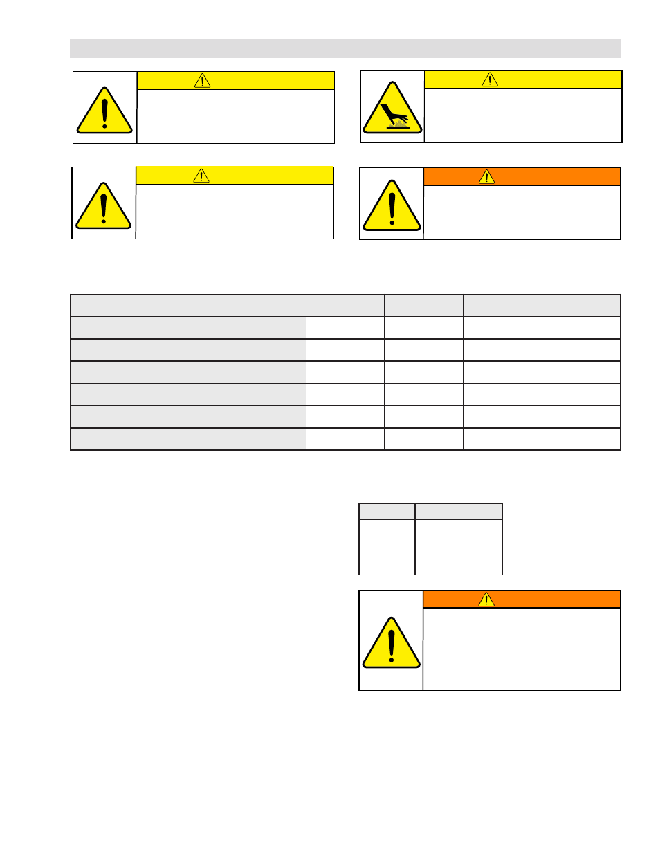
CAUTION
The temperature limits for this
product line are 4.5-104 Degree
Celsius (40-220 Degree F).
CAUTION
Prior to placing DPB Brake into service,
verify that all screws are secured to the
recommended torque (See Table 2).
WARNING
The outer assembly of the DPB Brake
rotates. A guard that will not restrict
the flow of cooling air around the brake
must be installed if the DPB Brake is
installed in an area where injury to an
operator could occur.
WARNING
Never exceed maximum operating
speeds listed for your product.
(See Table 3).
CAUTION
Never exceed life of facing material. Facing
life depends on the volume of material and
the total energy over the life of the unit.
Expected life (in hrs) can be found by:
Time=Volume/(Power*Wear Rate).