Nexen FMCBES-8-42 801481 User Manual
Page 12
FORM NO. L-20241-G-1209
12
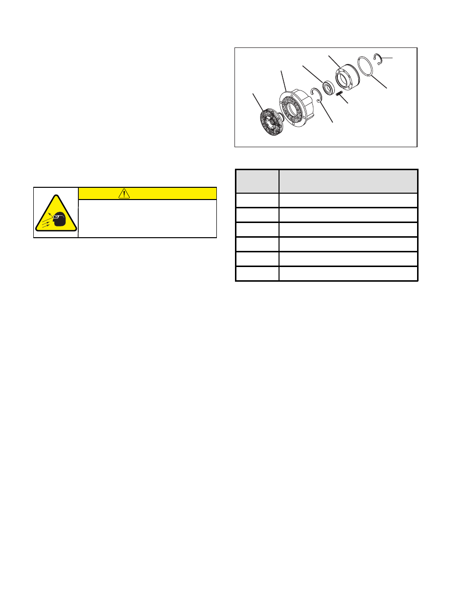
15
13
6/21
9
2/31
17
3/19
16
FIGURE 11
FMCBES
MODEL
RECOMMENDED TIGHTENING TORQUES
SOCKET HEAD CAP SCREW (ITEM 8)
130-19
14.2 Nm [10.5 ft-lb]
130-24
14.2 Nm [10.5 ft-lb]
7-28
33.2 Nm [24.5 ft-lb]
7-38
33.2 Nm [24.5 ft-lb]
8-38
67.1 Nm [49.5 ft-lb]
8-42
67.1 Nm [49.5 ft-lb]
TABLE 2
Refer to Figure 11.
4. Using a “C”-clamp or arbor press with fixture, press the
Piston (Item 15) into the Air Chamber (Item 13); then,
remove the Retaining Ring (Item 21 for Model 7-38
and Item 6 for all other Models) from the Splined Disc
(Item 9).
5. Supporting the Air Chamber (Item 13) and Piston
(Item 15), press the Splined Disc (Item 9) from the
Bearing (Item 31 for Model 7-38 and Item 2 for all
other Models).
6. Slowly remove the “C”-clamp or arbor press with
fixture.
17. Reinstall the Compression Springs (Item 17) into the
Piston (Item 15).
18. Slide the Piston (Item 15) into the Air Chamber (Item
13).
19. Use a “C”-clamp or arbor press with fixture to
compress the Piston (Item 15) into the Air Chamber
(Item 13).
20. Support the inner race of the new Bearing and press
the Splined Disc into the new Bearing and Piston.
21. Reinstall the Retaining Ring (Item 21 for Model 7-38
and Item 6 for all other Models) that secures the
Splined Disc to the Bearing.
22. Remove the “C”-clamp or arbor press with fixture.
23. Apply a drop of Loctite 242 to the threads of the
Socket Head Cap Screws (Item 14 for Models 130-
19 and 130-24 and Item 8 for all other Models).
24. Reinstall and tighten the four Socket Head Cap
Screws, securing the Air Chamber (Item 13) to the
Housing (Item 7) to the recommended torque (See
Table 2).
7. Remove the Piston (Item 15) and Compression
Springs (Item 17) from the Air Chamber (Item 13).
8. Remove the Retaining Ring (Item 19 for Model
7-38 and Item 3 for all other Models) from the
Piston.
9. Remove the old O-Ring Seal (Item 16) from the
Piston.
10. Press the Bearing (Item 31 for Model 7-38 and Item
2 for all other models) out of the Piston (Item 15).
11. Clean the bearing bore of the Piston with fresh
safety solvent, making sure all old Loctite
residue is
removed.
12. Apply an adequate amount of Loctite®
680 to evenly
coat the outer race of the new Bearing.
13. Carefully align the outer race of the new Bearing
(Item 31 for Model 7-38 and Item 2 for all other
Models) with the bore of the Piston (Item 15).
14. Supporting the Piston and pressing on the outer race
of the new Bearing, press the new Bearing into the
Piston.
15. Reinstall the Retaining Ring (Item 19 for Model 7-38
and Item 3 for all other Models), securing the Bearing
to the Piston.
16. Coat the O-Ring contact surfaces of the Air Chamber,
Piston, and the O-Ring Seal with a thin film of O-Ring
lubricant and install the new O-Ring Seal (Item 16).
PARTS REPLACEMENT –PISTON BEARING AND O-RING SEALS (continued)
CAUTION
Working with spring loaded or tension
loaded fasteners and devices can cause
injury. Wear safety glasses and take the
appropriate safety precautions.
- FMCBES-8-42 801482 FMCBES-130-19 801466 FMCBES-130-19 801467 FMCBES-130-24 801469 FMCBES-130-24 801470 FMCBES-7-38 801475 FMCBES-7-38 801476 FMCB/E-625 801721 FMCBES-110-14 801451 FMCBES-110-14 801452 FMCBES-7-28 801472 FMCBES-7-28 801473 FMCBES-8-38 801478 FMCBES-8-38 801479 FMCBES-110-14 801401 FMCBES-130 801402 FMCBES-7-38 801661 FMCBES-7-28 801662 FMCBES-8-38 801664 FMCBES-8-42 801405