Nexen FMCBES-8-42 801481 User Manual
Page 8
FORM NO. L-20241-G-1209
8
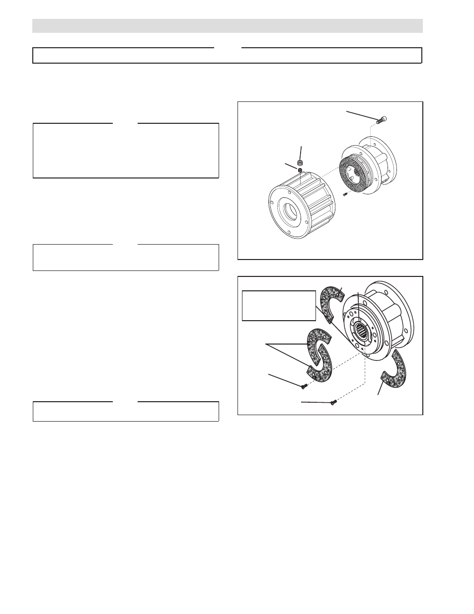
Socket Head Cap Screw
(Item 14)
Plug
(Item 35)
Set Screw
(Item 34)
FIGURE 4
PARTS REPLACEMENT–FRICTION FACINGS
FMCBES 110-14, 130-19, AND 130-24
Refer to Figures 4 & 5.
NOTE
If an Input Unit is installed on the FMCBES, it must
be removed before servicing the FMCBES. Remove
the Plug (Item 35) and loosen the Set Screw
(Item 34) to release the FMCBES from the Input
Unit shaft.
1. Remove the four Socket Head Cap Screws (Item 14)
and separate the two halves of the FMCBES.
2. Remove the six old Flat Head Screws (Item 12) and
the first old split Friction Facing (Item 11).
NOTE
Apply sufficient air pressure to the brake to release
the brake portion of the FMCBES.
3. Align the holes in the Splined Disc (Item 9) with the
Flat Head Screws (Item 12) that secure the second
split Friction Facing (Item 11).
4. Remove the six old Flat Head Screws (Item 12) and
the second old Friction Facing (Item 11).
5. Install the first new split Friction Facing (Item 11) and
new Flat Head Screws (Item 12).
6. Tighten the six new Flat Head Screws (Item 12) to 22
In. Lbs. [2.5 N•m] torque.
NOTE
Release the air pressure to the FMCBES.
7. Install the second new split Friction Facing (Item 11)
and new Flat Head Screws (Item 12).
8. Tighten the six new Flat Head Screws (Item 12) to 22
In. Lbs. [2.5 N•m] torque.
9. Apply a drop of Loctite 242 to the threads of the
Socket Head Cap Screws (Item 14).
10. Install and tighten the four Socket Head Cap Screws
(Item 14), securing the two halves of the FMCBES to
10.5 Ft. Lbs. [14.2 N•m] torque for Model 110-14 and
24.5 Ft. Lbs. [33.2 N•m] torque for Models 130-19
and 130-24.
FIGURE 5
11
11
Insert screwdriver
to remove second
split Friction Facing.
11
12
12
9
NOTE
The following sections are arranged by model. Verify that you are in the correct section for your model.
- FMCBES-8-42 801482 FMCBES-130-19 801466 FMCBES-130-19 801467 FMCBES-130-24 801469 FMCBES-130-24 801470 FMCBES-7-38 801475 FMCBES-7-38 801476 FMCB/E-625 801721 FMCBES-110-14 801451 FMCBES-110-14 801452 FMCBES-7-28 801472 FMCBES-7-28 801473 FMCBES-8-38 801478 FMCBES-8-38 801479 FMCBES-110-14 801401 FMCBES-130 801402 FMCBES-7-38 801661 FMCBES-7-28 801662 FMCBES-8-38 801664 FMCBES-8-42 801405