Installation – Nexen FMCBES-8-42 801481 User Manual
Page 5
5
FORM NO. L-20241-G-1209
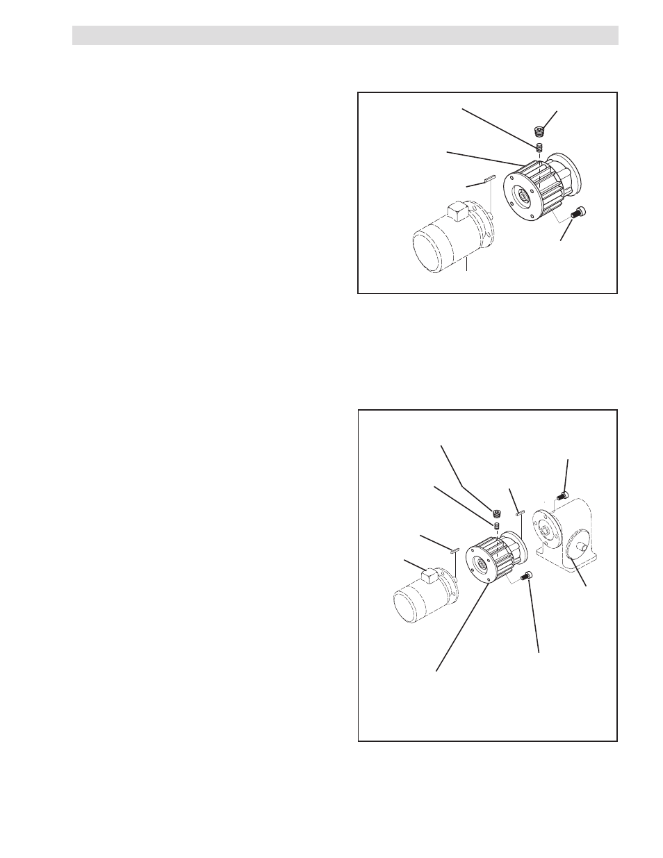
INSTALLATION
MOUNTED ON THE SHAFT END OF A MOTOR
Refer to Figure 1.
1. Insert the customer supplied key into the motor shaft
keyway.
2. Slide the FMCBES onto the motor shaft, then secure
it to the motor using customer supplied socket head
cap screws and lock washers.
3. Align the hole in the FMCBES Housing with the Set
Screw in the Drive Disc.
4. Tighten the Set Screw (Item 34) and then install the
Plug (Item 35).
MOUNTED BETWEEN A GEAR REDUCER AND A MOTOR
FIGURE 2
Motor
Customer
supplied key
Set Screw
(Item 34)
Plug
(Item 35)
Key
(Item 26)
Gear
Reducer
Customer supplied
socket head cap screws
FMCBES
Housing
Customer supplied
socket head cap screw
Refer to Figure 2.
1. Insert the Key (Item 26) into the output shaft of the
FMCBES.
‘
2. Slide the FMCBES output shaft into the gear
reducer.
3. Secure the FMCBES to the gear reducer using
customer supplied socket head cap screws, lock
washers, and nuts.
4. Insert the customer supplied key into the motor shaft
keyway.
5. Slide the motor into the FMCBES and secure it to the
FMCBES using customer supplied socket head cap
screws and lock washers.
6. Align the hole in the FMCBES Housing with the Set
Screw in the Drive Disc.
7. Tighten the Set Screw (Item 34) and then install the
Plug (Item 35).
FIGURE 1
Customer supplied
socket head cap screw
Set Screw
(Item 34)
Motor
Customer supplied key
FMCBES
Housing
Plug
(Item 35)
- FMCBES-8-42 801482 FMCBES-130-19 801466 FMCBES-130-19 801467 FMCBES-130-24 801469 FMCBES-130-24 801470 FMCBES-7-38 801475 FMCBES-7-38 801476 FMCB/E-625 801721 FMCBES-110-14 801451 FMCBES-110-14 801452 FMCBES-7-28 801472 FMCBES-7-28 801473 FMCBES-8-38 801478 FMCBES-8-38 801479 FMCBES-110-14 801401 FMCBES-130 801402 FMCBES-7-38 801661 FMCBES-7-28 801662 FMCBES-8-38 801664 FMCBES-8-42 801405