Installation – Nexen DFC-1650 964161 User Manual
Page 2
2
FORM NO. L-20272-E-1199
INSTALLATION
NOTE
The Pilot Housing has a 1/2-13 UNC tapped hole on
its outside diameter. A lifting ring may be threaded
into this hole to aid in the mounting/dismounting of
the clutch.
1.
Apply a drop of Loctite
®
242 to the threads of the eight
0.500-13 x 1.500" customer supplied socket head cap
screws and lock washers; then, secure the sheave to
the clutch (See Figure 1).
2.
Alternately and evenly tighten the eight Socket Head
Cap Screws to 114 Ft. Lbs. [153.83 N•m] torque.
3.
Insert the customer supplied key into the motor shaft
(See Figure 2).
NOTE
The motor shaft must be the proper size to allow
installation of the clutch onto the motor shaft. The
shaft bore of the clutch is machined to nominal
motor shaft sizes
+0.001
/
-0.000
''. Refer to Figure 3 for
maximum and minimum motor shaft insertions.
4.
Slide the clutch onto the motor shaft (See Figures 2
and 3).
5.
Apply a drop of Loctite
®
242 to the threads of the three
Set Screws (Items 24 and 33); then, insert and tighten
the three Set Screws (See Figure 2).
NOTE
Properly align sheave and tension the belts (see belt
and sheave manufacturer tightening and alignment
specifications).
CAUTION
Failure to align the sheaves will adversely affect
clutch and motor bearing life, compromise belt
wear, and cause belt squeal and vibration which
leads to belts turning over and/or being thrown
from the drive.
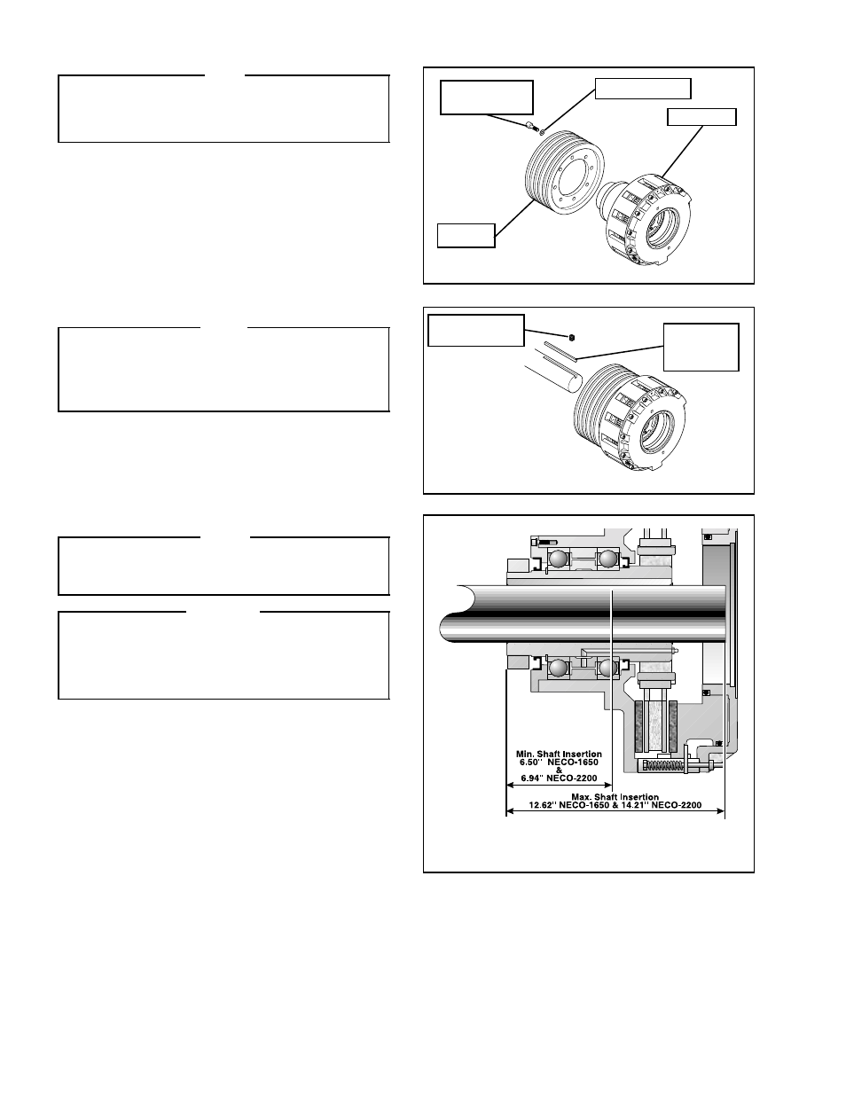
FIGURE 1
FIGURE 2
FIGURE 3
Customer
supplied
key
Lock Washer
Socket Head
Cap Screw
Sheave
Clutch
Set Screw
(Items 24 and 33)