Nexen DFC-1650 964161 User Manual
Page 7
7
FORM NO. L-20272-E-1199
19. Apply a drop of Loctite
®
242 to the threads of the
twelve Socket Head Cap Screws (Item 14) (See
Figure 9).
20. Install the twelve Socket Head Cap Screws (Item 14)
and Lock Washers (Item 20) (See Figure 9).
21. Alternately and evenly tighten the twelve Socket Head
Cap Screws to 110 Ft. Lbs. [148.43 N•m] torque.
22. Install the Hex. Head Torque Nuts (Item 19) (See
Figure 9).
23. Tighten the Hex. Head Torque Nuts (Item 19) until a
spring working height of 2.13 In. [51.2 mm] is achieved
(See Figure 10).
12. Tighten the new Flat Head Screws (Item 13) to
16 Ft. Lbs. [21.59 N•m] torque (See Figure 9).
13. Remove the old O-Ring Seal (Item 15) from the
Piston/Pressure Plate (Item 6) (See Figure 9).
14. Coat the new O-Ring Seal (Item 15) with Parker
®
O-Ring lubricant and install the new O-Ring Seal on
the Piston/Pressure Plate (Item 6) (See Figure 9).
15. Slide the Piston/Pressure Plate (Item 6) back into the
Pilot Housing (Item 2) (See Figure 9).
16. Remove the old O-Ring Seal (Item 17) from the
Cylinder (Item 5) (See Figure 9).
17. Coat the new O-Ring Seal (Item 17) with Parker
®
O-Ring lubricant and install the new O-Ring Seal on
the Cylinder (Item 5) (See Figure 9).
18. Slide the Cylinder (Item 5) onto the Piston/Pressure
Plate (Item 6) and Pilot Housing (Item 2) (See
Figure 9).
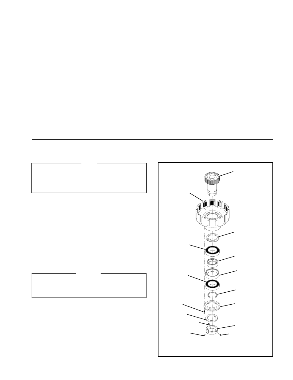
BALL BEARING and ROTARY SEAL REPLACEMENT
NOTE
The clutch must be removed from the motor to
replace the Ball Bearings and Rotary Seals. Two
1/2''-13 tapped holes are provided in the Hub to aid in
removing the clutch from the motor shaft and lifting
the Hub out of the Pilot Housing.
1.
Proceed with Steps 1-6 of FRICTION FACING and
O-RING SEAL REPLACEMENT, Page 6.
2.
Remove the Socket Head Cap Screws securing the
Sheave to the clutch and remove the Sheave.
3.
Remove the three Set Screws (Items 24 and 33) and
the Hub Locking Collar (Item 23) (See Figure 11).
4.
Remove the six Socket Head Cap Screws (Item 26)
(See Figure 11).
5.
Remove the Seal Seat (Item 22) and the old Rotary
Seal (Item 7) (See Figure 11).
WARNING
Special attention should be exercised when working
with retaining rings. Always wear safety goggles
when working with spring or tension loaded fasteners
or devices.
6.
Remove the Retaining Ring (Item 21) (See Figure 11).
7.
Press the Hub (Item 1) out of the Ball Bearings (Item 12)
and Pilot Housing (Item 2) (See Figure 11).
8.
Press the two old Ball Bearings (Item 12) and Spacers
(Items 16 and 34) out of the Pilot Housing (Item 2) (See
Figure 11).
9.
Press the old Rotary Seal (Item 27) out of the Pilot
Housing (Item 2) (See Figure 11).
FIGURE 11
23
26
22
7
21
12
12
27
2
1
16
34
24
33
33