Parts replacement – Nexen DFC-1650 964161 User Manual
Page 6
6
FORM NO. L-20272-E-1199
PARTS REPLACEMENT
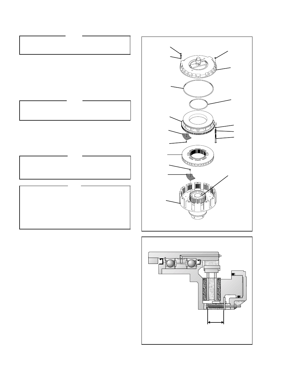
FRICTION FACING and O-RING SEAL REPLACEMENT
FIGURE 9
FIGURE 10
19
14
20
5
15
17
6
18
10
11
4
3
13
3
13
1
2
2.13
± 0.02
In.
Spring Working Height
NOTE
The clutch does not have to be removed from the
motor shaft to replace the Friction Facings and
O-Ring Seals.
1.
Remove the Hex. Head Torque Nuts (Item 19) (See
Figure 9).
2.
Remove the twelve Socket Head Cap Screws (Item 14)
and Lock Washers (Item 20) (See Figure 9).
3.
Remove the Cylinder (Item 5) (See Figure 9).
NOTE
Applying low air pressure aids in the separation of
the Cylinder (Item 5) from the Piston/Pressure Plate
(Item 6) (See Figure 9).
4.
Slide the Piston/Pressure Plate (Item 6) out of the Pilot
Housing (Item 2) (See Figure 9).
5.
Slide the Drive Disc (Item 4) off the Hub (Item 1) (See
Figure 9).
NOTE
If the Ball Bearings (Item 12) and Rotary Seals
(Items 7 and 27) are being replaced, proceed
w i t h B A L L B E A R I N G a n d R OTA RY S E A L
REPLACEMENT, Page 7.
NOTE
The Flat Head Screws (Item 13) are assembled with
an anaerobic thread locking compound. Inserting a
properly fitting screwdriver into the head of the Flat
Head Screw and striking the end of the screwdriver
with a hammer will break the crystalline structure of
the locking compound and allow removal of the Flat
Head Screws. Never use an impact wrench to remove
the Flat Head Screws.
6.
Remove the old Flat Head Screws (Item 13) and the
old Friction Facings (Item 3) from the Pilot Housing
(Item 2) (See Figure 9).
7.
Using new Flat Head Screws (Item 13), install the new
Friction Facings (Item 3) (See Figure 9).
8.
Tighten the new Flat Head Screws (Item 13) to
16 Ft. Lbs. [21.59 N•m] torque (See Figure 9).
9.
Slide the Drive Disc (Item 4) back onto the Hub (Item 1)
(See Figure 9).
10. Remove the old Flat Head Screws (Item 13) and the
old Friction Facings (Item 3) from the Piston/Pressure
Plate (Item 6) (See Figure 9).
11. Using new Flat Head Screws (Item 13), install the new
Friction Facings (Item 3) (See Figure 9).