Nexen FMBS-1375 801981 User Manual
Page 10
10
FORM NO. L-21272-A-1212
1. Remove the Retaining Rings (Item 11 & 12).
2. Press the Shaft (Item 1) out of Bearings (Item 10)
towards the input side of the brake.
3. Remove the four Hex Head Cap Screws (Item 26) and
Lock Washers (Item 27).
4. Remove the Input Housing (Item 6).
5. Remove the four Socket Head Cap Screws (Item 25).
6. Remove the Air Cylinder (Item 2).
7. Remove the O-Ring Seals (Items 20 & 21).
8. While supporting the Disc Plate (Item 4), compress the
Piston (Item 3) to remove the axial load on the Splined
Disc (Item 5).
9. Remove only the Retaining Ring (Item 15) from the
O.D. of the Splined Disc (Item 5).
10. Slowly press the Splined Disc (Item 5) out of the Bearing
(Item 13), while still supporting the Disc Plate (Item 4).
11. Slowly separate the Piston (Item 3) and the Disc Plate
(Item 4).
12. Remove the Compression Springs (Item 22).
13. Remove the Retaining Ring (Item 14).
14. Using a bearing puller, remove the Bearing (Item 13)
from the Piston (Item 3).
15. Using a bearing puller, remove the Bearings (Item 10)
from the Air Chamber (Item 2).
16. Clean the bearing bore of the Piston (Item 3) and the Air
Chamber (Item 2) with fresh safety solvent to remove
all old Loctite® residue.
17. Clean the o-ring grooves, contact surfaces, and spring
pockets of the Piston (Item 3) and the Air Chamber
(Item 2).
18. Apply an adequate amount of Loctite® 680 to evenly
coat the O.D. of two new Bearings (Item 10) and press
both new Bearings into Air Chamber (Item 2).
19. Reinstall Retaining Ring (Item 11).
20. Apply an adequate amount of Loctite® 680 to evenly
coat the O.D. of new Bearing (Item 13) and press new
Bearing into Piston (Item 3).
21. Reinstall Retaining Ring (Item 14).
22. Equally space the Compression Springs (Item 22) in
the spring pockets of Piston (Item 3). Compression
Spring quantity shown in Table 4.
23. Slide the Piston (Item 3) onto the Dowel Pins (Item 23)
of the Disc Plate (Item 4).
24. Press the Splined Disc (Item 5) into the new Bearing
(Item 13) and maintain clamping force.
25. Reinstall Retaining Ring (Item 15) and slowly release
clamping force.
26. Lubricate the new O-ring Seals (Items 20 & 21) and
o-ring contact surfaces with a thin film of fresh O-ring
lubricant.
27. Install the new O-ring Seals (Items 20 & 21).
28. Slide the Air Chamber (Item 2) onto the Piston (Item
3).
NOTE: Avoid pinching of O-ring Seals when assembling
the Piston and Air Chamber.
29. Apply Loctite® 242 to the threads of the Socket Head
Cap Screws (Item 25) then alternately and evenly tighten
them to 325 in-lbs (36.7 Nm).
30. Secure the Disc Plate (Item 4) to the Input Housing
(Item 6) using Hex Head Cap Screws (Item 26) and
Lock Washers (Item 27).
31. Tighten Hex Head Cap Screws (Item 26) to 200 in-lbs
(22.6 Nm).
32. Align the external splines of the Shaft (Item 1) with the
internal splines of the Splined Disc (Item 5) and press
the Shaft (Item 1) into new Bearings (Item 10) towards
the output side of the brake.
33. Reinstall Retaining Ring (Item 12).
CAUTION
Special attention should be exercised when
working with Retaining Rings. Always wear
safety goggles when working with spring or
tension loaded fasteners or devices.
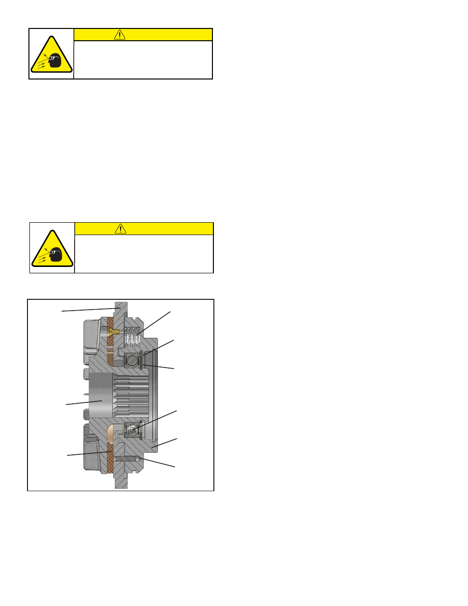
CAUTION
Piston, Disc Plate, and Splined Disc are
spring loaded. Components can spring apart,
resulting in personal injury if Piston and Disc
Plate are not clamped together. (See Figure 7)
FIGURE 7
Disc Plate
(Item 4)
Splined Disc
(Item 5)
Friction Facing
(Item 18)
Compression Spring
(Item 22)
Retaining Ring
(Item 14)
Retaining Ring
(Item 15)
Bearing
(Item 13)
Piston
(Item 3)
Dowel Pin
(Item 23)