Nexen TCC Caliper 835121 User Manual
Page 11
8
FORM NO. L-20065-K-0110
AIR CONNECTIONS continued
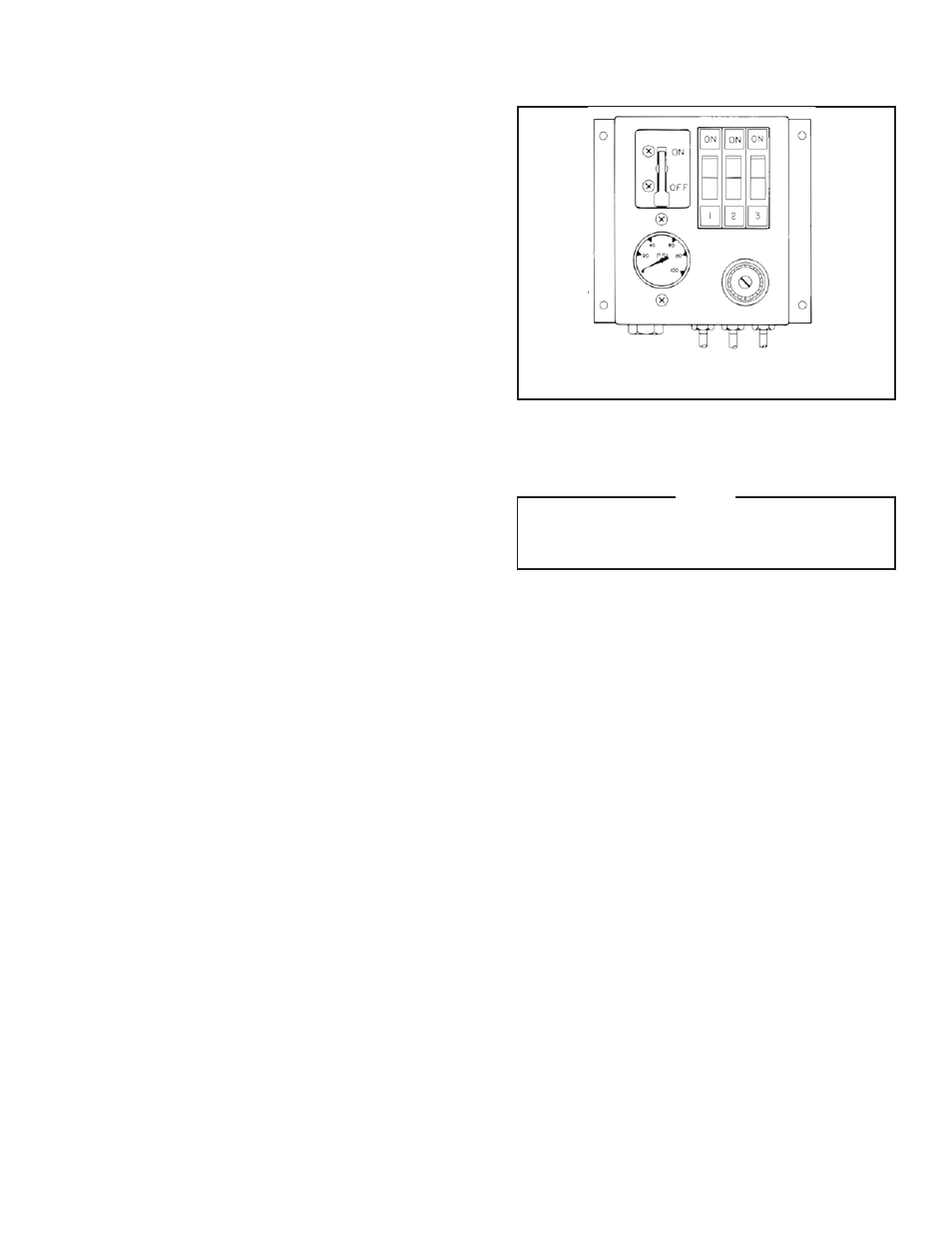
FIGURE 11
MULTIPLE CALIPER CONNECTIONS
The 3-Stage Caliper Control (Product No. 835120) directs
air pressure to three separate sets of calipers connected as
a single pair or a series. This provides three torque ranges
with just one brake for handling a variety of web materials.
It consists of a 3-Way, ON/OFF toggle switch, a pressure
regulator, a 0-100 psi pressure gauge, and three rocker
switch valves which allow the user to select caliper operat-
ing stages to vary torque output (See Figure 11).
Figure 12 shows typical caliper connections for the TCB-
10, TCB-14, and TCB-20. The 3-Stage connections shown
are examples of how calipers are arranged when controlled
by the 3-Stage Caliper Control.
Any number of calipers may be used in each stage. By
activating switch 1, 2, or 3, two or all three switches vary the
torque output to meet a predetermined braking requirement.
1. Install a Tee Fitting into each half of one caliper (See
Figure 12, Stage III for your model).
2. Connect caliper halves together using 13 1/2"
[342.9 mm] length of Air Line (See Figure 12, Stage
III for your model).
3. Install two Tee Fittings in the next set of calipers.
Cut lengths of Air lines to make bridge connections
between the Tee Fittings.
4. Install an Elbow and Tee Fitting into the last set of
calipers. Make a bridge connection between the Tee
Fittings in the previous caliper (See Figure 12, Stage
III for your model).
5. Connect opposite end of Tee Fitting to 3-Stage
control outlet.
6. Repeat Steps 1-5 for each set of calipers connected
in series.
7. Connect air supply to control inlet port and set
regulator to desired air pressure (See Figure 13).
3-Stage Caliper Control, Product No. 835120
NOTE
See Figures 12 & 13 on the following page for
Caliper Connections and Air Line Connections
drawings.