Altera MAX 10 Embedded Memory User Manual
Page 33
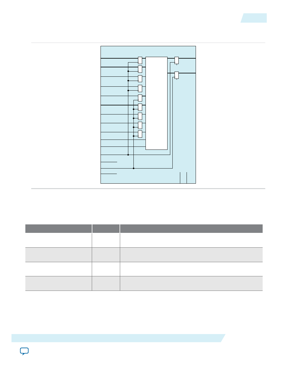
Figure 5-6: RAM: 2-Port IP Core Signals with the Two Read/Write Ports and Dual Clock: Use Separate for
A and B Ports Options Enabled
data_a[]
wren_a
data_b[]
address_b[]
addressstall_a
clock_a
enable_a
clock_b
enable_b
q_a[]
aclr_a
address_a[]
wren_b
addressstall_b
rden_a
rden_b
byteena_a[]
aclr_b
q_b[]
RAM: 2-Ports IP Core Signals (Simple Dual-Port RAM) For MAX 10 Devices
Table 5-1: RAM: 2-Ports IP Core Input Signals (Simple Dual-Port RAM)
Signal
Required
Description
data
Yes
Data input to the memory. The
data
port is required and the
width must be equal to the width of the
q
port.
wraddress
Yes
Write address input to the memory. The
wraddress
port is
required and must be equal to the width of the
raddress
port.
wren
Yes
Write enable input for
wraddress
port. The
wren
port is
required.
rdaddress
Yes
Read address input to the memory. The
rdaddress
port is
required and must be equal to the width of
wraddress
port.
UG-M10MEMORY
2015.05.04
RAM: 2-Ports IP Core Signals (Simple Dual-Port RAM) For MAX 10 Devices
5-5
RAM: 2-PORT IP Core References
Altera Corporation