User-defined leds, Power supply, Power measurement – Altera MAX 10 FPGA User Manual
Page 21: User-defined leds –9, Power supply –9, Power measurement –9
Chapter 3: Board Components
3–9
Power Supply
October 2014
Altera Corporation
MAX 10 FPGA (10M08S, 144-EQFP) Evaluation Kit
User Guide
User-Defined LEDs
The development board includes five user-defined LEDs. Board references D1
through D5 are user LEDs that allow status and debugging signals to be driven to the
LEDs from the designs loaded into the MAX 10 FPGA device. The LEDs illuminate
when a logic 0 is driven, and turns off when a logic 1 is driven. There is no
board-specific function for these LEDs.
Table 3–5
lists the user-defined LED schematic signal names and their corresponding
MAX 10 FPGA pin numbers.
Power Supply
The development board is powered up through a USB cable. The green LED
illuminates when the board is powered up.
Power Measurement
In order to measure the actual power of the FPGA, there are test pads on the board to
be used as probe points for multi-meter probes. The user can measure the current and
using the equation P = R x I
2
. (Power = Resistance x Current Squared), calculate the
power dissipation.
Test pads TP2 and TP3 are used to measure the current consumed by the FPGA core.
Test pads TP4 and TP5 are used to measure the current consumed by all of the FPGA's
I/O banks. All the other test pads are used to verify the voltage levels of various
nodes on the board.
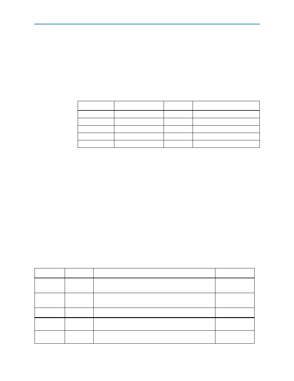
Table 3–5. User-Defined LED Schematic Signal Names and Functions
Board Reference
Schematic Signal Name
I/O Standard
MAX 10 FPGA Device Pin Number
D1
LED1
2.0-V
132
D2
LED2
2.0-V
134
D3
LED3
2.0-V
135
D4
LED4
2.0-V
140
D5
LED5
2.0-V
141
Table 3–6. Power Measurement Details
Test Pad #’s
Measuring
Description
Expected Value
TP2 - TP3
FPGA core
current
Power calculation for FPGA Vcc-core power consumption.
Resistor R1 = 0.1 ohms. Current measured by user's multi-meter.
___ mWatts
TP4 - TP5
FPGA I/O
current
Power calculation for FPGA Vcc-io power consumption.
Resistor R4 = 0.1 ohms. Current measured by user's multi-meter.
___ mWatts
Test Pad #’s
Measuring
Description
Expected Value
TP1
Board input
voltage
Verify the USB input voltage
5.0-volts
TP6
Analog
voltage
Verify the proper voltage required by the FPGA Vcca inputs
3.3-volts