Configuration, status, and setup elements, Configuration, Configuration, status, and setup elements –17 – Altera 100G Development Kit, Stratix IV GT Edition User Manual
Page 25: Configuration –17
Chapter 2: Board Components
2–17
Configuration, Status, and Setup Elements
September 2010
Altera Corporation
100G Development Kit, Stratix IV GT Edition Reference Manual
lists the MAX II CPLD EPM2210 System Controller component reference
and manufacturing information.
Configuration, Status, and Setup Elements
This section describes the board’s configuration, status, and setup elements.
Configuration
The Stratix IV GT 100G development board supports three configuration methods:
■
Embedded USB-Blaster is the default method for configuring the FPGA at any
time using the Quartus II Programmer in JTAG mode with the supplied USB cable.
■
MAX II+Flash Fast Passive Parallel (FPP) download is used for configuring the
FPGA using stored images from flash memory on either power-up or pressing the
load (S11) push-button.
U72.P6
User push-button
Input
USER_PB1
—
S3.2
U72.T4
User push-button
Input
USER_PB2
—
S2.2
U72.R7
User push-button
Input
USER_PB3
—
S1.2
U72.N3
Indicates which user Programmer
Object File (.pof) is loaded into the
FPGA
Output
USER1_POF
—
D19.2
U72.N5
Output
USER2_POF
—
D20.2
U72.N2
Output
USER3_POF
—
D25.2
U72.M4
Indicates that factory .pof is loaded
into the FPGA
Output
FACTORY_POF
—
D26.2
U72.H1
LCD control signals
Output
LCD_CSn
—
J59.6
U72.G7
Output
LCD_D_Cn
—
J59.4
U72.J3
Output
LCD_WEn
—
J59.5
U72.G6
LCD data bus
Output
LCD_DATA0
—
J59.7
U72.H2
LCD data bus
Output
LCD_DATA1
—
J59.8
U72.G5
LCD data bus
Output
LCD_DATA2
—
J59.9
U72.H3
LCD data bus
Output
LCD_DATA3
—
J59.10
U72.G4
LCD data bus
Output
LCD_DATA4
—
J59.11
U72.G1
LCD data bus
Output
LCD_DATA5
—
J59.12
U72.F6
LCD data bus
Output
LCD_DATA6
—
J59.13
U72.G2
LCD data bus
Output
LCD_DATA7
—
J59.14
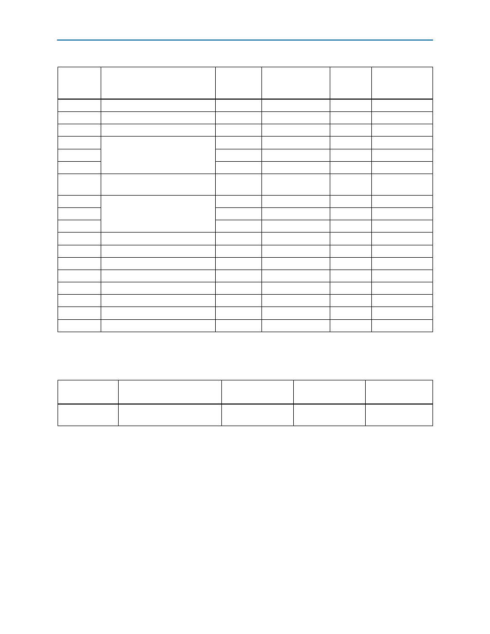
Table 2–5. MAX II CPLD EPM2210 System Controller Device Pin-Out (Part 6 of 6)
EPM2210
Pin Number
Description
Type
Schematic Signal
Name
Stratix IV
GT Device
Pin Name
Other
Connections
Table 2–6. MAX II CPLD EPM2210 System Controller Component Reference and Manufacturing Information
Board Reference
Description
Manufacturer
Manufacturing
Part Number
Manufacturer
Website
U72
IC - MAX II CPLD EPM2210
256FBGA -3 LF 1.8V VCCINT
Altera
Corporation
EPM2210F256C3N