Altera Stratix II EP2S180 DSP Development Board User Manual
Page 14
2–6
Core Version a.b.c variable
Altera Corporation
Stratix II EP2S180 DSP Development Board Reference Manual
Nonvolatile Configuration
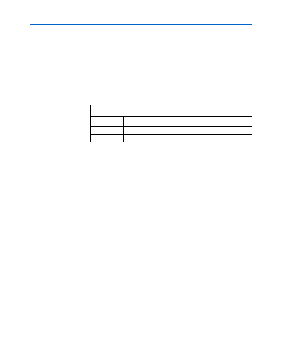
DIP switches 1 through 3 on SW2 select one of four possible Stratix II
configuration images upon power-up. When DIP switch 4 is in the
“OPEN” position the configuration controller is enabled. If DIP switch 4
is in the “OPEN” position and there are no valid user-defined images, the
Stratix II device is programmed with the factory configuration.
shows the DIP switch combinations used to select the available images.
See
“Nonvolatile Configuration” on page 2–5
for more details.
1
Switch 4 of the SW2 DIP switch must be set to “OPEN” to enable
the configuration controller.
1
An alternative method of configuring the device with the
factory design is to press push-button switch SW3.
You can load a customized user design or reload a factory design into the
on-board flash memory by using the Nios II Flash Programmer in the
Nios II SDK Shell.
Programming Example for the
2S180 DSP Development Board
The following example instructions illustrate how to program the 2S180
DSP Development Board.
1.
Generate a flash file to load into the flash device.
a.
Run the NIOS II SDK Shell.
b.
Change directories to the project location.
c.
Run the sof2flash utility:
$ sof2flash --input=<project_name>.sof --
output=<project_name>.flash --offset=0x00900000
You can use the offset switch to specify which configuration area of the
flash will be loaded. Use 0x00900000 for User0 area, or 0x00200000 to
overwrite the Factory.
2.
Copy the flash file into the on-board flash device.
Table 2–2. Configuration DIP Switch (SW2) Combinations
Image
Switch 1
Switch 2
Switch 3
Switch 4
User0
Closed
Closed
Closed
Open
Factory
Open
Open
Open
Open