D/a converters – Altera Stratix II EP2S180 DSP Development Board User Manual
Page 27
Altera Corporation
Core Version a.b.c variable
2–19
Stratix II EP2S180 DSP Development Board Reference Manual
Board Components & Interfaces
D/A Converters
The Stratix II EP2S180 DSP development board has two D/A converters.
The D/A subsystem of the board has the following features:
■
The converters produce 14-bit samples at a maximum rate of 165
MSPS.
■
The analog output from each D/A converter is single-ended.
1
The D/A converters expect data in an unsigned integer format.
The D/A clock signals are output directly from the Stratix II device to the
converters.
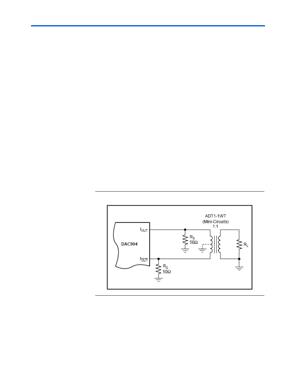
Figure 2–5
shows the on-board circuitry after a D/A converter. The
output of a D/A converter chip, DAC904, consists of a current source
whose maximum value is 20 mA. This differential output is converted to
a single -ended output using an RF transformer. The DSP board uses a 1:1
ratio transformer to interface to a 50 ohm impedance load. Each of the
outputs is terminated with a 49.9 ohm resistor to ground. This circuit
results in outputs being AC-coupled and inherently isolated due to
transformer’s magnetic coupling. The output of the transformer is then
brought to an SMA connector.
Figure 2–5. On-Board Circuitry after D/A Converter
1
The development kit includes an SLP-50 anti-aliasing filter from
Mini-Circuits. This filter provides a 55-MHz cut-off frequency.
For systems with other bandwidth requirements, a variety of
anti-aliasing filters are available from commercial
manufacturers that suit system requirements.