Dual channel receiver – MIPRO act707de(2ce143d) User Manual
Page 3
2
3
DUAL CHANNEL RECEIVER
DUAL CHANNEL RECEIVER
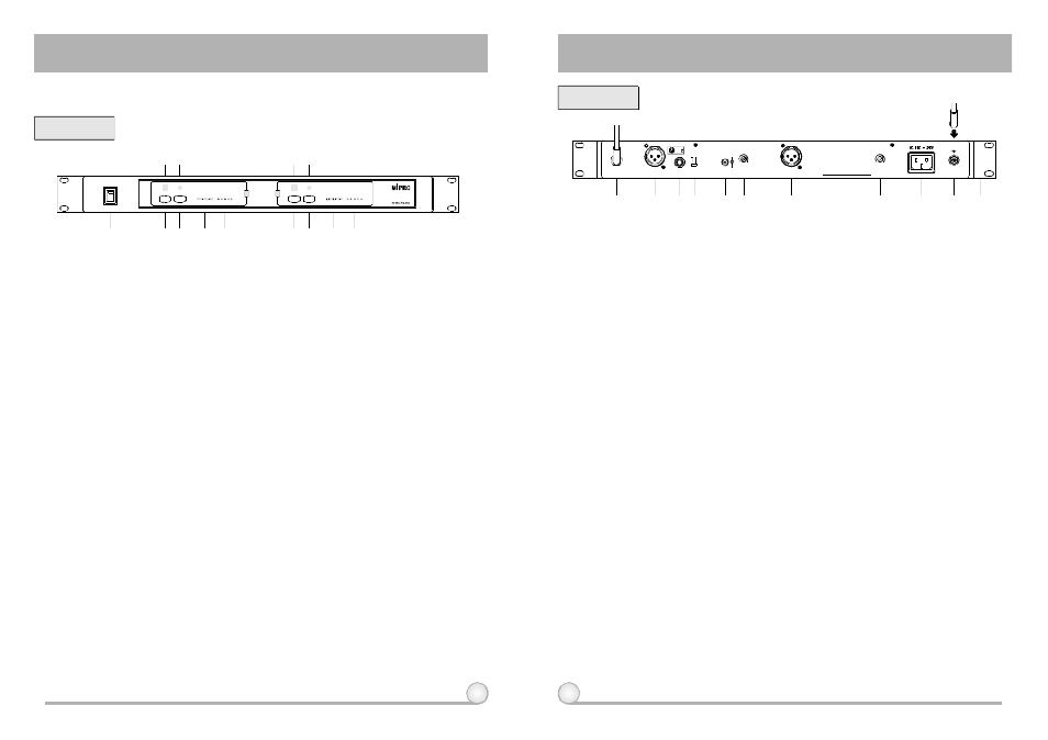
2. PARTS NAMES AND FUNCTIONS
Front Panel:
Rear Panel:
(Fig.1)
(Fig.2)
POWER
(1)
( 2 )
(3)
(4)
(5)
(6)
(7)
(8)
(9)
(10)
(11)
(12)
(13)
ACT-707DE
SCAN
SCAN
ACT
A C T
RF
RF
AUDIO
AUDIO
SIGNAL
SIGNAL
A
B
(24)
+ 8 V D C B I A S
3:COLD
1:GND
2:HOT
MADEINTAIWAN
S Q B
B A L A N C E D O U T A
DCIN(12~15V)
LEVEL
M I X O U T
A N T E N N A B
B A L A N C E D O U T B
S Q A
A N T E N N A A
MIC
L I N E
+ 8 V D C B I A S
(14)
(15) (16)(17)
(18) (19)
(20)
(21)
(22)
(23)
(1)
Power Switch & Indicator: When switch is turned on, red indicator
illuminates to denote normal powerstatus.
(2)(8)
Audio Signal Level Indicator: Indicate theaudio signallevel.
(3)(9)
RFSignal Level Indicator: Indicate the RFsignal strength received.
(4)(10)
ACT Button: To setupmicrophone frequency tomatch receiver
frequency.
(5)(11)
Scan Button: Press once to selectreceiving channel and autoscan
the whole bandwidth to avoid interference channel.
(6)(12)
ACT Indicator : Indicate if ACT function isactivated.
(7)(13)
Channel Indicator: Todisplaysystem's receiving channel.
(14)
Rear Antenna B input Connector: B Antenna connector can be
installed withantenna directly and provides power for antenna
booster..
(15)(20) Balanced A udio Output Jack: With Cannon / XLR type connector
provides balanced audio output signal from this jack to theamplifier.
(16)
UnbalancedAudio Mixed Output Jack : With 1/ 4
Phone Jack
provides the mixed unbalanced audio output signal from this jack to
the amplifier. Switch between "LINE" and "MIC" for different purposes.
(17)
Unbalanced Level Switch: "MIC" selection is for "Microphone-level"
output. "LINE" selection is for "Line-out" level output.
(18)
DC 12V Input Jack: To connect 12 VDC from the AC/DC adapter.
(19)(21) Squelch Adjuster: Adjust the squelch level to eliminate the RF noise
interference at receiver stand-bystate.
(22)
AC Input Jack: To connect 85 ~ 265 VoltsACpower.
(23)
Rear Antenna A input Connector: A Antenna connector can be
installed withantenna directly and provides power for antenna
booster.
(24)
Rackmount Bracket: To install the receiver into an EIA 19-inch
standard rack case.
λ
Switchbetween "LINE" and "MIC" for different purposes.