Belt pack transmitter – MIPRO act707de(2ce143d) User Manual
Page 8
1
2
3
5
8
7
4
6
9
10
ACT
BELT PACK TRANSMITTER
BELT PACK TRANSMITTER
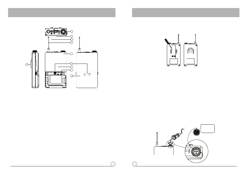
1. PARTS NAMES AND FUNCTIONS
(Fig.1)
(Fig.2)
1.
AF Input Jack: Connects to either lavaliere or headset microphone. (See
5 ways o f connection o n AF Input Connections)
2.
PowerSwitch: Switch to ON position for operation. Switch to OFFposition
when not in use.
3.
Battery Status Indicator: Indicates the power on / off and battery status.
(a) When power switch is turned on: The LED indicator flashes briefly,
indicating normal battery status.
(b) When RED light illuminates at either power o n or during usage: The
battery level is low, therefore, a new battery replacement is thus
necessary.
4.
Transmitting Antenna: 1/ 4
transmitting antenna.
5.
Transmitter Housing: Packages the P C B a n d battery.
6.
Act Signal Receptor
7.
Gain Control: Adjusts the desirous input gain.
8.
GT/MT Level Select Switch: Switch GT position for electric guitarusage
and "Line In". Gain Control is irrelevant for "GT". Switch to "MT" for
condenser microphone or wired microphone. Gain Control works in "MT"
for input sensitivity adjusting.
λ
9.
Battery Compartment and Cover: Accommodates one 9 Volt battery.
10. DetachableBelt Clip: Allows 360 degrees rotating to suit transmitting
angles. To detach simply use a screwdriver at a 45 degree angle to
unfasten. see diagram.
2. OPERATING INSTRUCTIONS
1.
To adjust GT/MT Switch (8), and Gain Control (7), simply pushdown both
snap locks on the sides o f battery cover and flip it backwards to expose
the adjustment panel.
2.
Before power on,ascertain if same channel was set up for both receiver
and microphone. If not adjust to same channel accordingly.
3.
The LED indicator flashes briefly when power on indicating normal battery
status. If no flash occurs it has either no battery, the battery isdrained or
installed incorrectly. Change accordingly.
4.
Plug the microphone connector into the input jack (1) and tighten the
connector screw by clockwise direction as shown in (Fig. 2).
Lavalier
Headset
Pleaseaimof
thefillister
andinsertthe
connector
1 2
13
CapsuleConnector