Dual channel receiver – MIPRO act707de(2ce143d) User Manual
Page 4
4
5
(Fig.3)
(Fig.4)
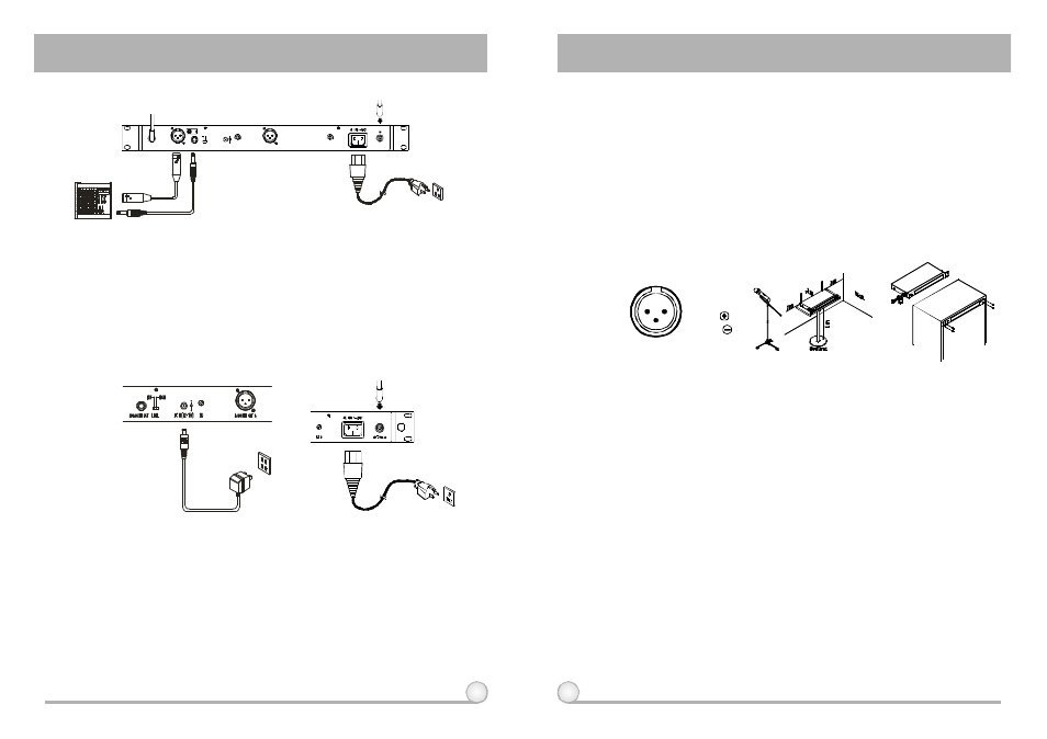
3. INSTALLATION OF THE RECEIVER
1.
Install 2 separate antennas o n the antenna sockets (14), (23) on the rear
panel. Illustrated in figure 3.
2.
PowerOutput Connection:
(a)
Unbalanced Level Switch (17) Setting Position: When inputs the unbalanced
output of a receiver into "AUX-IN" input jack of a mixer or amplifier or
"Electric Guitar", switch the Level Switch (17) to the right "LINE" position.
MIC sensitivity may occur if switch to the wrong position. When input the
unbalanced output of a receiver into the "MIC-IN" input jack of a mixer or
amplifier; switch the Level Switch (17) to the left "MIC" position. Overload
distortion may occur if switching to the wrong position. When using electric
guitar, don't use "MIC" position as it may have generated insufficient level.
(b)
Unbalanced Output: Using audio output cable attached with "PHONE PLUG"
type, connect one end from the unbalanced output jack (16) of the receiver,
and the other end to the "LINE-IN" input jack of the amplifier, as shown in
Fig. 3.
(c)
Balanced Output: Using audio output cables attached with "XLR" or
"Cannon" type, connect one end from the balanced output jacks (15)(20) of
the receiver, and the other end to the "MIC IN" input jack of the mixer or
amplifier, as shown in Fig. 3. (The characteristic of the 3-pin connector is as
shown in Fig. 6
(d)
Guitar Output: Using audio output cable attached with "PHONE PLUG" type,
plug one end from the unbalanced output jack of a receiver, and the other
end to the input jack of a guitar amplifier. Switch the Level Switch (17) to
"LINE" position.
(Fig.6)
3.
Audio Output Connection:
(a)
Connect the AC/DC adapter cable to DC 12V INPUT JACK (18), then plug
the adapter unit into an appropriate AC outlet with caution to the correct
voltage under both AC outlet and adapter marked, as shown in fig. 4.
(b)
With the appropriate AC power cable connects from AC Input Jack (22) to an
AC outlet under the marked voltage 85~265 V, as shown in Fig. 5.
(Fig.5)
3: COLD
1:GND
2:HOT
3
2
1
(Fig.8)
(Fig.7)
4.
To ensure best reception possible, receiver must be installed at least one
meter above ground. In addition, the distance between transmitter and
receiver must be more than one meter and away from noise. (Shows in
figure 7)
5.
On the front panel of the receiver, 4 openings are pre-drilled for instant
installation on the standard 19-inch rack case. (Shows in figure 8)
+8VDCBIAS
3:COLD
1 : G N D
2:HOT
MADEINTAIWAN
S Q B
B A L A N C E D O U T A
DCIN(12~15V)
LEVEL
M I X O U T
A N T E N N A B
B A L A N C E D O U T B
S Q A
ANTENNAA
M I C
LINE
+ 8 V D C B I A S
DUAL CHANNEL RECEIVER
DUAL CHANNEL RECEIVER