Connecting input signals, Inputs 5 volt digital inputs – Applied Motion BLuDC4-Si User Manual
Page 10
10
10
10
10
10
BLuDC-Si Hardware manual
BLuDC-Si Hardware manual
BLuDC-Si Hardware manual
BLuDC-Si Hardware manual
BLuDC-Si Hardware manual
OUT1+
OUT1-
OUT2+
OUT2-
OUT3+
OUT3-
OUT4+
OUT4-
IN1
COM
IN2
IN3
COM
IN4
CWLIM+
CWLIM-
CCWLIM+
CCWLIM-
CWJOG
COM
CCWJOG
+5V
AIN
GND
Outputs
Single Ended
Inputs
Differential
Inputs
Single Ended
Inputs
Analog
Input
Upper “Screw Terminal” Input/Output Connector
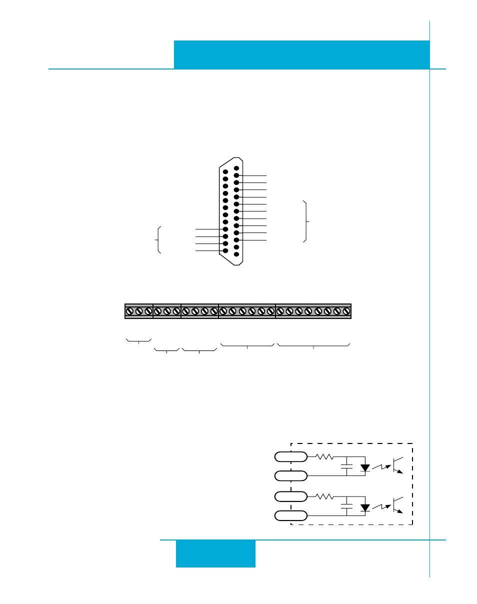
5 Volt Digital Inputs
The BLU-Si includes two high speed inputs called X1 and X2. They accept 5 volt single-ended or
differential signals, up to 2 MHz. You can connect a master encoder to the high speed inputs for
following applications using the Hand Wheel instruction. Or
you can use X1 and X2 as general purpose inputs for Wait
Input, If Input, Feed to Sensor or Seek Home instructions.
Connection diagrams for inputs X1 and X2 follow.
inside BLU Servo
330
220 pF
X1+
X1-
330
220 pF
X2+
X2-
12
11
10
9
Connecting Input Signals
Inputs
The BLUDC-Si drives include 15 digital inputs. Some of these inputs appear on the lower board
“DB-25” connector and the rest are on the upper board “screw terminal” connector.
Lower Board “DB-25” Connector
X COMMON
X7
X6
X3
X5
X4
X2-
X2+
X1+
X1-
Front View
12
11
10
9
8
7
6
5
4
3
17
16
15
14
Shared
Common
Shared
Common
Y1/BRAKE
Y2/INPOSN
Y3/ALARM
Y COMMON