Wiring a limit sensor programmable outputs – Applied Motion BLuDC4-Si User Manual
Page 16
16
16
16
16
16
BLuDC-Si Hardware manual
BLuDC-Si Hardware manual
BLuDC-Si Hardware manual
BLuDC-Si Hardware manual
BLuDC-Si Hardware manual
Programmable Outputs
The BLU-Si drives feature seven digital outputs:
Brake/Y1
Brake/Y1
Brake/Y1
Brake/Y1
Brake/Y1: controls an electric brake relay, automatically releasing and engaging as the drive
requires
Alarm/Y2
Alarm/Y2
Alarm/Y2
Alarm/Y2
Alarm/Y2: closes when a drive fault or alarm condition occurs. The red and green LEDs will flash
an error code.
In Position/Y3
In Position/Y3
In Position/Y3
In Position/Y3
In Position/Y3: indicates that the drive has achieved a desired goal, such as a target position.
Y1, Y2 and Y3 can be configured as dedicated, automatic Brake, Fault and In Position outputs or
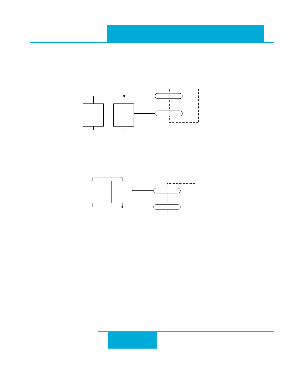
Wiring a Limit Sensor
Some systems use active limit sensors that produce a voltage output rather than a switch or relay
closure. These devices must be wired differently than switches.
If your sensor has an open collector output or a sinking output, wire it like this:
BLU Servo
Si board
+
DC
Power
Supply
–
Limit
Sensor
output
+
–
CW LIMIT+
CW LIMIT-
If the sensor output goes low at the limit, select the option “closed” (in the software). If the output
is open, or high voltage, choose “open”.
Other sensors have sourcing outputs. That means that current can flow out of the sensor output,
but not into it. In that case, wire the sensor this way:
If the sensor output goes high at the limit, choose the program option “closed”. If the output is low
at the limit, select “open”.
",5
3I
$#
0OWER
3UPPLY
n
0ROXIMITY
3ENSOR
OUTPUT
n
#7
#7