CIRCUTOR EDMk Series User Manual
Edmk manual, Three phase meter edmk
EDMk Manual
THREE PHASE METER EDMK
The EDMk three-phase electronic energy meter is capable
of measuring consumed and generated energy (four
quadrants): Active energy (consumed and generated),
inductive reactive energy (consumed and generated) and
capacitive reactive energy (consumed and generated), plus
metering partial energies.
Measurements are in true effective value, via three AC.
voltage and neutral inputs and three AC. current inputs. (via
…/5A, …/1A or .../250mA for MC3 current transformers).
The parameters measured and calculated are shown in
the variables table
This manual describes how to configurate and use the
EDMk energy meter. This manual may be found in
electronic format on the CIRCUTOR website:
www.circutor.com
Before any maintenance, modification to
the connections, repair, etc., the equipment
must be disconnected from the supply. If any
operation or protection fault is suspected the
equipment must remain out of service ensuring against
any accidental reconnection. The equipment is designed
to changed quickly in the event of any breakdown
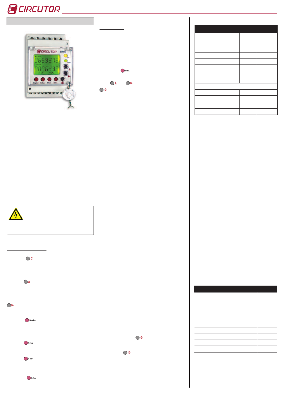
1. KEYBOARD FUNCTION.
The button
allows the user to move through the
different energy groups (if any): tariff one and partial tariff,
or tariff one, two, three and partial tariff (EDM3k type). It
used in the set up menu it is used to enter the data and
move on to the next parameterisation screen.
The button
allows the active or reactive energy display
options to be displayed. It is used in the set up menu
to increase the value by one digit if a variable has been
entered or selected.
Generated or consumed energy can be selected using
in the option. Inductive or capacitive energy can be
selected in the reactive option. In the set up menu is used
to move the cursor among the digits.
The button
allows the display to come on in the
absence of any power supply. This function allows the on
site reading of meters when the device is out of service.
This option is available when the meter has an optional
station installed inside (see price list M3).
The button
allows a quick access to the device’s full
parameterisation menu. To access this menu, press the
button for less than one second.
The button
deletes partial energies. To do this, press
the button for less than 4 seconds. The message will then
display “donE”, indicating that these meters have been
successfully started (active and reactive).
The button
starts the meter in one step only
with the minimum setting for the meter. (see section
Parameterisation in one step only).
2. STARTING UP
2.1. Previous information
2.2. Parameterization in one step only
This option is only valid for installations where there
is no voltage transformer to measure. Voltage is only
measured directly (300V AC f-N / 500V AC f-f) and current
measurement is via secondary external current transformers
of .../1A, .../5A or in model MC of .../250 mA.
Keeping the
button pressed for 1 second, the
energy meter enables the current primary and secondary
parameterisation on screen.
Using
and
buttons the value of the current
transformer primary and secondary is validated using thel
button.
3. COMPLET MENU
Using the complete parameterisation of the meter, all
setting options can be set. These options affect the setting
of the external voltage transformers, if any, as well as the
omission of energy meters which the customer believes to
of little relevance or are not required in their installation.
3.1. Voltage transformer
On screen the words “
Pri U
” appear followed by 6 digits.
These allow the voltage transformer primary to be set
(from
1
to
999.999
).
On screen the words “
SEC u
” appear followed by 3 digits.
These allow the voltage transformer secondary to be set
(from
1
to
999
).
3.2. Current transformer
On screen the words “
Pri A
” appear followed by 4 digits.
These allow the current transformer primary to be set (from
1
to
9.999
).
On screen the words “
SEc A
” appear followed by the
number 5 or 1. These allow the installed current transformer
secondary ratio to be set (
5
=…/ 5A or
1
=…/ 1A).
* The option secondary in model MC does not exist (is
allways 250mA)
3.3. Measurement in 2 or 4 quadrants
On screen the words “
QuAd
” appear; one of the two
available options must be selected:
2
= power consumption
or
4
= consumption and generation.
3.4. Backlight disconnection time setting
On screen the words “
diSP
oFf
” appear; the time the
backlight is on can be set after pressing the keypad. The
backlight is permanently on if
00
is set.
3.5. Display or not reactive energy
On screen the words “
rEACt
” appear; this option allows the
reactive energy to be displayed or omitted (“
YeS
” or “
nO
”).
3.6. Display partial energy counters
On screen the words “
PArt
” appear; this option allows the
partial active and reactive energy to be displayed or omitted
(“
YeS
” or “
nO
”). In the event of omission, the meter does
not show energy and stops metering energy.
3.7. Energy output pulse settings
The screen shows “
Out ACt
”; the energy to be associated
to digital output 1 must be selected: Consumed active
energy (
import
) or generated (
export
); once the data
has been entered with
button, the W•h value must
be entered by pressing.The screen shows “Out rEA”: the
reactive energy to be associated to digital output 2 must be
selected: L / C- / L- / C; once the data has been entered
with the button
, the var•h value must be entered by
pressing the keypad. In case of selecting 2 quadrants (see
section 3.3. Measurement in 2 or 4 quadrants), only are
available
L
or
C
.
4. DEFAULT SETTINGS
The EDMk-ITF-C2 electronic three-phase meter is supplied
with the following default settings:
VARIABLE
POINT
VALUE
Primary voltage
3.1
000001
Secondary voltage
3.1
001
Primary current
3.2
0005
Secondary current
3.2
5 / 0.250 A
Measure in 2 or 4 quadrants
3.3
2
Backlight disconnection
3.4
10
Reactive energy display
3.5
no
Partial energy counters
3.6
no
Energy pulses
- Active energy
3.7
IMPORT
- w·h / pulse
3.7
1000
- Reactive energy
3.7
L
- var·h / pulse
3.7
1000
5. TARIFFS (EDM3K MODEL)
The tariff time is carried out using hardware. The
equipment has a common and two inputs free of voltage
to select the type of tariff required (Tariff 1, Tariff 2 or Tariff
3).
- Tariff 1: Without any bridge between terminals
- Tariff 2: Bridge between terminal A and S
- Tariff 3: Bridge between terminal B and S
6. COMMUNICATIONS (RS-485 C2 MODEL)
6.1. Programming parameters
Confi gurable parameters in the parameterisation menu:
- “
nPEr
”: Peripheral number 001 to 255
- “
bAud
”: Baud rate 1200-2400-4800-9600-19200
- “
bitS
”: Length 8 bits
- “
PAri
”: No, Even, Odd
- “
StoP
”: Stop bits 1 or 2
Default settings
001
/
9600
/
8
/
N
/
1
6.2. Communication protocol
The EDMk meter uses MODBUS RTU © communication
protocol and network protocol RS-485. The format is as
follows:
QUESTION: NP FT AAAA NNNN CRC
NP:
1 Byte
Peripheral number
FT:
1 Byte
Function 04 reading of n Words
AAAA:
2 Bytes
Address of 1st register
NNNN:
2 Bytes
Number of regiters to be requested
CRC:
1 Byte
Cyclic Redundancy Checking
In the MODBUS © recordings, the energy is accumulated in
kW•h x 100 (2 decimal points) with a length of 2 Words.
6.3. Modbus/RTU © memory map
PARAMETER
REGISTER
Active Energy (+)
00-01
Active Energy (-)
02-03
Inductive reactive energy (+)
04-05
Capacitive reactive energy (-)
06-07
Inductive reactive energy (-)
08-09
Capacitive reactive energy (+)
0A-0B
Partial active energy (+)
30-31
Partial activ energy (-)
32-33
Partial inductive reactive energy (+)
34-35
Partial capacitive reactive energy (-)
36-37
Partial inductive reactive energy (-)
38-39
Partial capacitive reactive energy (+)
3A-3B
M98204801-03-11A
The device has to be provided of an magnetic-thermal
switch to be disconnected. The fuses has to be type gl
(IEC 269) or type M between 0,5 to 2 A.
6.4. Communications connections
Description of connection for the RS-485 bus, for
communication via an Intelligent Converter (485-RS232), or
via an Ethernet Converter (Transparent / Modbus/TCP).