CIRCUTOR computer MAX Plug&Play series User Manual
Page 6
M98228201-03-14A
computer
MAX
6 / computer
MAX
12
- 6 -
Program 1:1:1. All capacitor stages have the same rated power (kvar). For instance, a 5-stage unit of
100 kvar would be formed by 5 equal stages of 20 kvar and would be described as a unit of (5 x 20) kvar.
Program 1:2:2. All capacitor stages from the second and up have a rated power (kvar) which is twice the
rated power of first stage. For instance, a 5-stage unit of 180 kvar would be formed by a first stage of 20
kvar and 4 equal stages of 40 kvar, and would be described as a unit of (20 + 4 x 40) kvar.
Program 1:2:4. The rated power of the second stage is twice the rated power of the first stage and the
rated power of third stage and up is 4 times the power of the first stage. For instance, a 5-stage unit of
300 kvar would be formed by a first stage of 20 kvar, a second stage of 40 kvar and 3 equal stages of 80
kvar, and would be described as a unit of (20 + 40 + 3 x 80) kvar.
Other switching programs. Other switching programs are also commonly available, like 1:2:2:4 or
1:1:2:2, etc. Abbreviated designation form, as can be deduced from previous cases, consists of a
sequence of numbers giving the relationship between the different stage powers (kvar), and the first
stage power, which value is taken as unit (1 ). The successive stages will be designated by 1, or 2 or 4,
etc. meaning that the kvar ratio of such stages with regard to first stage are equal, twice, four times, etc.
1.3.5 Plug & Play.
When a reactive energy regulator is installed, a series of parameters must be configured for its correct
operation. Some of these parameters might be hard to know, such as, for example, the voltage phases or
the voltage corresponding to the current measured, as well as the current transformer ratio. The
Computer MAX features a smart automatic process that detects the necessary parameters, such as:
- C/K: calculates the ratio between the current transformer and the power of the smallest step.
- Phase: identifies the phase sequence between voltages and the correspondence with the connected
current.
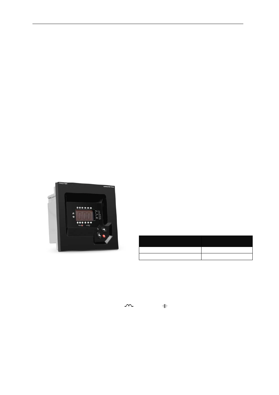
2 GENERAL
CHARACTERISTICS
The power factor regulators, of types Computer
MAX
6 and
MAX
12 measure the cos φ
(sometimes called Displacement Power Factor,
DPF) in a supply network and control the connection
and disconnection of power capacitors in order to
regulate such parameter.
The difference between the two types is the number
of output relays, which determines the number of
stages that they can control.
Type
MAXimum Nr of
output relays
computer
MAX
6
6 relay outputs
computer
MAX
12
12 relay outputs
Among the most important features of this PF regulator series we can stand out the following:
-
FCP regulation system, which minimizes the number of switching operations.
-
Wide choice of switching programs: 1:1:1, 1:2:2, 1:2:4 , 1:1:2:2, etc. which allows the split up of
the total power into up to 31 steps in
MAX
6
or up to 79 steps in MAX
12.
-
Four quadrants control (see fig.2.1) , display of the connected stages, of cos φ
and active and
reactive power signs
(inductive
or capacitive )
-
LCD display screen with three seven segments characters plus 20 icons to sign up the different
possible working conditions.
-
Regulator set-up with only three keys and without disconnecting the device from the supply.
-
Multiple supply frequency range, either 50 or 60 Hz
-
Main electrical parameters displayed during RUN mode
-
Easy panel mounting, without the need of tools.
-
Front frame size (144 x 144 mm) according to DIN 43 700 (panel hole 138
+1
x 138
+1
mm)
-
Measurement and power supply in one single input.
-
Four quadrant regulation (suitable for installations importing or exporting energy)