CIRCUTOR computer SMART Series (Available until stock) User Manual
Page 8
M98235701-03-12A
Computer Smart 6/Computer Smart 12
- 7 -
2
INSTALLATION AND START-UP
This section contains information and warnings that the user must respect at all times to guarantee his own
safety and the safe operation of the device.
WARNING! The Computer Smart regulators are connected to units with capacitors that
remain charged even after the voltage has been disconnected. Wait at least 5 minutes
after the equipment is disconnected, before the internal components of the equipment are
handled, in order to avoid the risk of electric shock.
Any manipulation or use of the equipment different from that specified by the
manufacturer may compromise user safety.
The power supply must be disconnected from the unit when it shows signs of deterioration or a faulty
operation. In this case, contact a qualified service representative.
The persons responsible for the installation or operation of the Computer Smart 6 or Computer Smart 12
regulator must follow the common safety measures for LV or MV installations to guarantee a safe operation,
depending on the installation location. In addition, they must take into account all safety warnings stated in
this instruction manual.
2.1
Technical features
The main features of the unit are marked on the label on the rear (see Fig. 1.1) and they are also described
in the quick guide attached. They are summarised in the following table:
Main power supply and
voltage measurement
480, 400, 230, or 110 Vac. +15 % -10 %; 50/60 Hz, (see label) Power supply: U
L1
-
U
L2
. Measurement U
L1
, U
L2
, U
L3
and U
N
Power supply cables
Section 1.5 mm2, gl 0.5 to 2 A protection fuse
Current measurement
circuit
Current transformer (CT), In /5 A AC., preferably on phase L1. Min. cable section.
2.5 mm2
Leakage current
measurement circuit
Nominal current of transformer secondary: I
∆
sec = 2 mA AC. Transformer with
ratio of 500: I
∆
= 1 A AC. +20%
Current measurement
margin
Current I: 0.05 ... 5 A AC (maximum overload +20%)
Leakage current I
∆
: 0.01 ... 1 A AC(maximum overload +20%)
Measurement accuracy
Voltage and current: 1%; cos
ϕ
: 2%
±
1 digit
Temperature
measurement
External temperature approximation. Range: 0 ... 80ºC. Accuracy:
±
3ºC
Consumption
8.2 VA (empty); 9.3 VA (6 relays); 11 VA (12 relays)
Output
Relays. Contacts for Umax. 250 Vac., 4 A AC., AC1.
Cabling and output relay
protection
Cable section 1.5 mm2, protection with circuit breaker (C curve) of 6 A or gl 6 A
fuse
Alarm relay
Switched relay for use exclusively for the alarms
Standards
IEC 62053-23 (2003-01) Ed. 1.0
IEC 61326-1, EN61010-1, UL 508
Safety/Insulation
Category III, Class II, according to EN 61010-1
Protection degree
IP40 (equipment mounted, cabinet front panel)
IP30 (equipment not mounted) according to EN-60529
Admissible
environmental conditions
Temperature: -20 ... +60ºC; Relative humidity: max. 95% (without condensation).
Max. altitude: 2000 m
Control system
FCP (a program that minimises the number of operations)
Communications
Interface: RS485. Protocol: MODBUS.
Speed: 9600, 19200, 38400
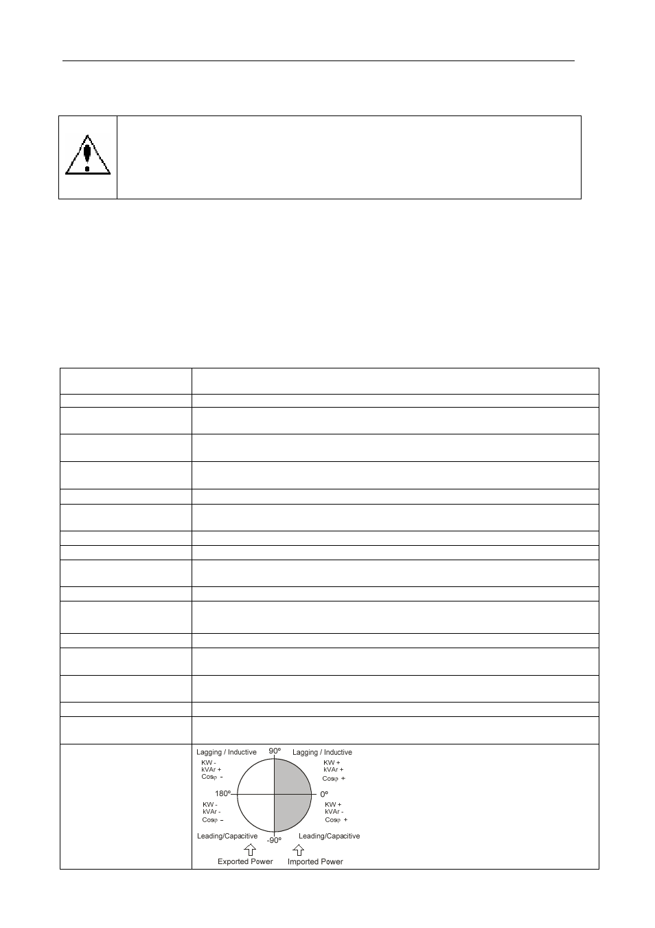
The Smart computer
regulator measures and
operates in 4 quadrants
according to the attached
diagram.