Power block – CIRCUTOR OPTIM-EMS-C Series User Manual
Page 9
Advertising
Th-D 1
Q
Th-D 2
PPPC1
PPPC2
U2
V2
W2
1
3
5
2
4
6
U1
U2
1
3
2
4
5
Radiador
V1
V2
1
3
2
4
5
PLACA
1G1
+
-
CPC4
CONTROL
1K1
PLACA
1G1
+
-
CPC4
CONTROL
1K1
12VDC
12VDC
Mando
Alimentación Potencia
Conexión a Condensador de 3 Bornes
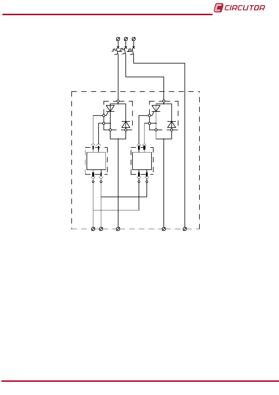
Figure 3: Basic connection diagram of the CPC4 to the power block.
2.1.3. POWER BLOCK
The power block of an
OPTIM EMS-C unit consists of 2 to 4 groups of thyristor-diode semicon-
ductors + three-phase capacitor + three-pole circuit breaker.
Each group is composed of a cylindrical capacitor with 3 terminals, 2 thyristor-diode modules
attached to a general heatsink and suitable protection elements for the module power (three-
pole circuit breaker).
9
Instruction Manual
OPTIM EMS-C series
Advertising