Warning, General information, Specifications – Computronic Controls Sentinel 150 User Manual
Page 3: Dc output calibration
Sentinel 150 installation, operation & maintenance
ci0033 p3/8 issue 4 2015-09-03
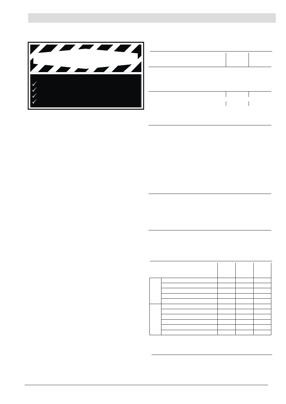
BEFORE BEGINNING INSTALLATION OF THIS PRODUCT
Disconnect all electrical power to the charger
Make sure the charger cannot operate during installation
Follow all safety warnings of the battery manufacturer
Read and follow all installation instructions
WARNING
The Sentinel 150 range provides automatic, current limited
and voltage controlled charging of wet lead acid, VRLA or
NiCd batteries. The units may be used in a wide range of
industrial charging applications, including standby
engines, pumps and generators.
Sentinel uses switch mode power supply technology to
give a compact and lightweight construction, improved
efficiency and low heat dissipation, wide supply voltage
tolerance and low output ripple.
Sentinel chargers are available as an open-frame module
(with protective cover) for surface or DIN rail mounting in
an enclosed panel, or as a stainless steel, wall-mounted
enclosure with DC charge ammeter (and voltmeter on
NFPA models). Electrical connection of the AC supply,
battery and control circuits is via screw terminal blocks.
Float charge operation
Sentinel operates an intelligent, multi-stage battery charge
regime. In normal charging mode, the charger maintains
the battery at a pre-calibrated float voltage (see table right),
while supplying any additional DC load up to the specified
current limit (see Specifications right).
When fully charged, a battery will only accept the charge
required to replace internal losses (approx. 1mA per AH of
battery). E.g. for a system with a 1 Amp standing load and
a fully charged 50 AH lead acid battery, Sentinel will
typically supply 1.05 Amps.
AutoBoost operation
All Sentinel 150 models include an AutoBoost feature.
AutoBoost provides a temporary increase in output
voltage, equalising the charge between cells and
maximising battery life and capacity.
AutoBoost is triggered automatically when the battery
falls below a preset voltage, or can be initiated manually
(whatever the battery voltage) via a momentary switch
input. Once the batteries have reached the boost voltage
level, Sentinel reverts to normal float charge mode,
preventing battery over-charge and gassing.
Temperature compensation
The optimum charge voltage for lead acid and NiCd
batteries varies with ambient temperature. Sentinel
can be configured to sense ambient temperature and
automatically compensate the output charge voltage.
Configuration is by links on the circuit board: temperature
compensation can be disabled, or enabled for use with a
remote ‘RTC’ sensor (available separately as a standard
3 metre / 9.8 feet lead assembly, or other lengths to
special order).
Alarm outputs
UL models include a self-diagnostic circuit charge fail /
main AC fail relay output (switched positive contact),
for driving a remote alarm or annunciator circuit.
Enclosed NFPA models include two additional relay outputs
(volt-free/dry contacts) for independent signalling of high
and low battery voltage faults, and compliance with the
NFPA 110 standard.
Specifications
power supply:
(E)SNTL(UL)
1501205
(E)SNTL(UL)
1502405
ESNTLUL
1501210
xxNFPA
operating voltage range:
standard (non-UL) models:
UL approved models
operating frequency
95
– 265 V AC
95
– 250 V AC
47
– 63 Hz
DC charge output:
nominal voltage
12
24
12
float / boost voltages
see DC output calibration table
current limit
5
5
10
line regulation
< 2%
load regulation
< 2%
output ripple
< 1%
alarm outputs:
charge fail /
mains AC failure
(UL models only)
solid state relay (switched +DC),
energised (+DC) during normal charge,
de-energised (open circuit) during fault
low battery volts
(NFPA models only):
solid state relay
(volt free/dry SPNC contacts),
energised (open) during normal charge,
de-energised (closed) during fault
high battery volts
(NFPA models only)
solid state relay
(volt free/dry SPNO contacts),
de-energised (open) during normal charge,
energised (closed) during fault
current rating (all relays)
250mA max. @ 30 V DC
(resistive load), UL class 2
general:
operating temperature
-20 to +60 °C / -4 to +140 °F
humidity
20% to 90% RH
dimensions
see Dimensions & Assembly
weights
see Dimensions & Assembly
electrical safety
2006/95/EC (EN 60065)
electromagnetic compatibility
2004/108/EC
(EN 61000-6-2, EN 61000-6-4)
UL approval:
All UL models:
BBGQ: UL1236,
CSA 22.2 no 107.2
ESNTLUL1501210xxNFPA
models only
BBHH: UL1236 SE
DC output calibration
Battery type:
model
option
code
float
volts
(V DC)
boost
volts
(V DC)
12V Vented lead acid (6 cells)
LA
13.5
14.1
Calcium-Calcium (6 cells)
CA
13.8
15.6
VRLA, AGM (6 cells)
AGM
13.5
14.4
VRLA, Gel (6 cells)
GEL
13.5
13.8
NiCd (10 cells)
10NC
14.1
14.5
24V Vented Lead acid (12 cells)
LA
27.0
28.2
Calcium-Calcium (12 cells)
CA
27.6
31.2
VRLA, AGM (12 cells)
AGM
27.0
28.8
VRLA, Gel (12 cells)
GEL
27.0
27.6
NiCd (18 cells)
18NC
25.6
26.1
NiCd (20 cells)
20NC
28.2
29.0
Note: Calibration figures at 20 deg C. Output voltage will vary if
temperature compensation is enabled
– see Electrical Connection &
Configuration section.
General Information
Please read the following before installing. A visual inspection of this product for damage during shipping is
recommended before installation. It is your responsibility to ensure that qualified mechanical and electrical
technicians install this product. If in doubt, please contact your local Computronic representative.