Dimensions and assembly – Computronic Controls Sentinel 150 User Manual
Page 4
Sentinel 150 installation, operation & maintenance
ci0033 p4/8 issue 4 2015-09-03
Dimensions and Assembly
CAUTION: Sentinel 150 chargers should be handled by the circuit board cover (SNTL models) or steel
enclosure (ESNTL models). Care should be taken not to handle static sensitive components through exposed
circuit boards and terminals.
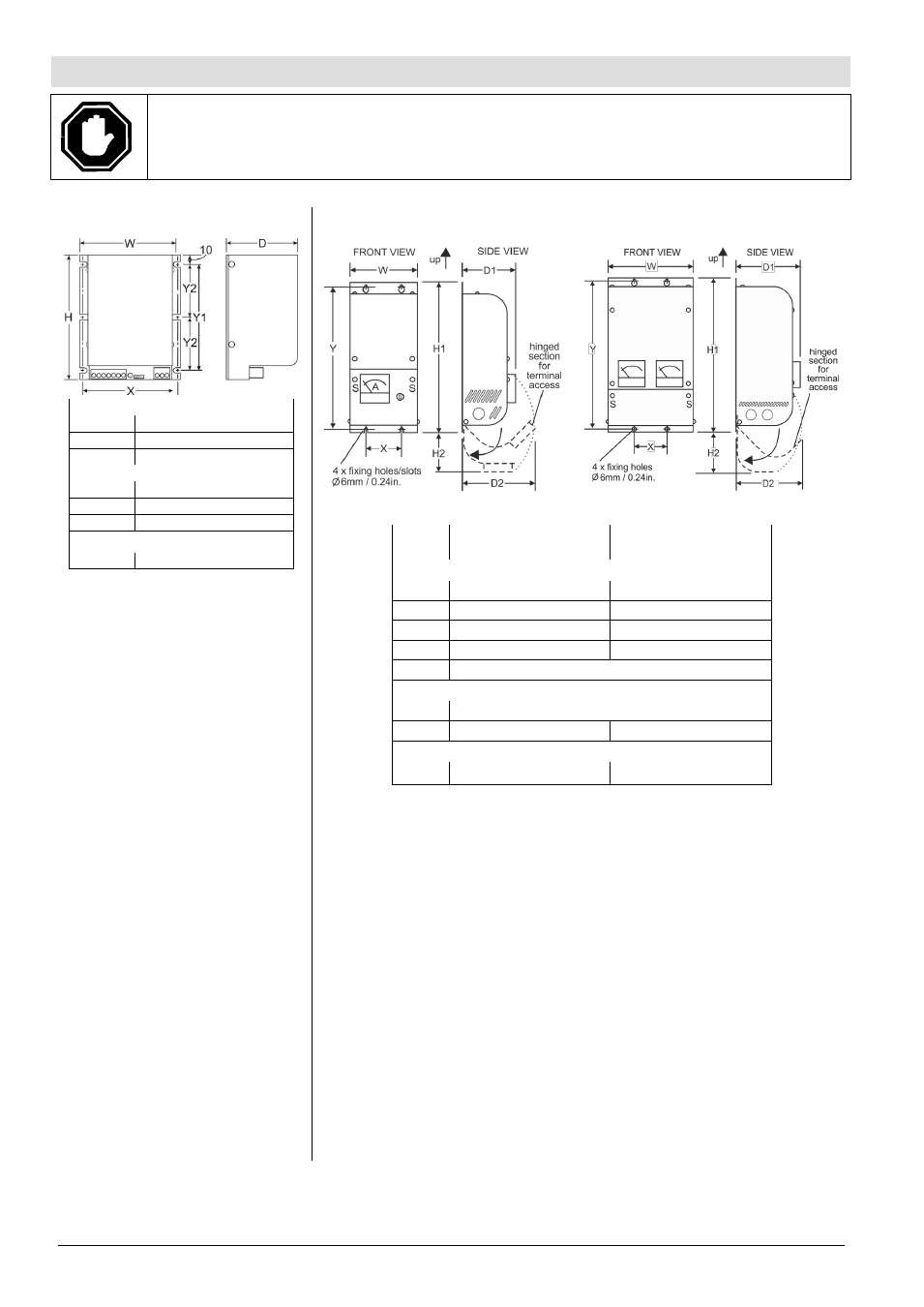
SNTL(UL)150xx models
Overall:
W
110 mm / 4.33 in.
H
135 mm / 5.31 in.
D
78 mm / 3.07 in.
Fixing holes:
X
100 mm / 3.94 in.
Y1
115 mm / 4.53 in.
Y2
57.5 mm / 2.26 in.
Weight:
0.55 kg / 1.2 lb.
These chargers are designed for
mounting in a vertical plane inside
an enclosed control panel or
housing. Mounting orientation
should be as shown above, with
protective cover ventilation slots at
the top & bottom, electrical
connection terminals lowermost.
For safe heat dissipation, mount
Sentinel in the orientation shown,
with a minimum air-gap clearance
of 40mm/1.5 in. above/below
and 25mm/1 in. at the sides.
Consideration must be given to
ventilation for proper heat
dissipation.
For surface mounting, use the
2 centre slots (Ø 6mm/0.24 in.) or
4 corner slots (Ø 6mm/0.24 in.).
Ensure that the mounting
studs/bolts/nuts/screws adequately
support the charger, and are
tightened sufficiently to not to
become loose during normal use,
e.g. due to engine/equipment
vibration.
Optional clip for DIN rail mounting
(2 required for each charger), part
number 045-0001.
ESNTL(UL)150xx models
ESNTLUL150xxNFPA models
ESNTL(UL)150xx
models
ESNTLUL150xxNFPA
models
Overall:
W
120 mm / 4.72 in.
165 mm / 6.50 in.
H1
267 mm / 10.51 in.
300 mm / 11.81 in.
H2
70 mm / 2.76 in.
80 mm / 3.15 in.
D1
95 mm / 3.74 in.
125 mm / 4.92 in.
D2
130 mm / 5.12 in.
Fixing holes:
X
63.5 mm / 2.50 in.
Y
255 mm / 10.04 in.
285.5 mm / 11.25 in.
Weight:
1.25 kg / 2.8 lb.
2.0 kg / 4.4 lb.
These chargers are designed for wall or frame mounting in the orientation shown
above, with enclosure air vents uppermost. For safe heat dissipation, allow a
minimum air-gap clearance of 40mm/1.5 in. above/below and 25mm/1 in. at the
sides. Consideration must be given to ventilation for proper heat dissipation.
Mounting is via the enclosure back-plate, using 4 holes/slots (Ø 6mm/0.24in.) on
the upper and lower edges. Ensure that the mounting studs/bolts/nuts/ screws
adequately support the charger weight, and are tightened sufficiently to not to
become loose during normal use, e.g. due to engine/equipment vibration.
Access to the electrical connection terminals is via hinged lower sections on the
front facia. Remove the 2 x securing screws (marked S above), and then rotate
the hinged sections through 90 degrees.
Electrical cable entry is via knock-outs on either side of the enclosure, which
must be carefully removed from the enclosure sides. A suitable cable-gland
(20mm/0.8in. diam.) must be used to prevent damage to cables and stop
unwanted entry into the inner part of charger. Cable harnesses for DC charge
output, DC control and AC supply input must be physically separated, e.g. using
separate harnesses and case access ports: see ‘wire harness separation’ section
on page 5.
Connect the charger wiring as detailed in the following Electrical Connection
section. When wiring is complete, and before using the charger, re-secure the
hinged front section using the 2 fixing screws.