Electrical connection & configuration (cont.) – Computronic Controls Sentinel 150 User Manual
Page 6
Sentinel 150 installation, operation & maintenance
ci0033 p6/8 issue 4 2015-09-03
DC Charge Output
Before DC connection or disconnection:-
Ensure AC supply input is isolated.
Disconnecting the batteries while the
AC supply is live can result in sparking at
the battery terminals, ignition of battery
gasses and serious personal injury.
Check that the charger model and output
ratings are compatible with battery type &
voltage (see table below). Incompatibility
may result in damage to the charger,
batteries and serious personal injury.
Connect the Sentinel DC charge output to the battery
terminals, observing the warnings above and the correct
DC polarity. Use 4mm²/11 AWG or larger wire for
ESNTLUL150xxNFPA models (10A DC output). For all
other models (5A DC output), use 2.5mm²/13 AWG or
larger wire.
All Sentinel 150 models include an electronic, self-resetting
DC output fuse for protection of reverse polarity and short-
circuit faults. In the event of such faults, isolate the AC
supply, disconnect the output terminals and allow the fuse
to self-reset; replacement of the fuse should not be
necessary. The charger can then be re-connected and
switched back on. If the fuse fails to reset, contact your
supplier for further advice.
Float & AutoBoost output voltages
The DC output float and AutoBoost voltages are factory
calibrated for the battery type specified at order. The
battery type is identified on the charger rating label, and
forms part of the model code. Standard calibrations are:
Battery type
model
option
code
float
volts
(V DC)
boost
volts
(V DC)
12V Vented lead acid (6 cells)
LA
13.5
14.1
Calcium-Calcium (6 cells)
CA
13.8
15.6
VRLA, AGM (6 cells)
AGM
13.5
14.4
VRLA, Gel (6 cells)
GEL
13.5
13.8
NiCd (10 cells)
10NC
14.1
14.5
24V Vented Lead acid (12 cells)
LA
27.0
28.2
Calcium-Calcium (12 cells)
CA
27.6
31.2
VRLA, AGM (12 cells)
AGM
27.0
28.8
VRLA, Gel (12 cells)
GEL
27.0
27.6
NiCd (18 cells)
18NC
25.6
26.1
NiCd (20 cells)
20NC
28.2
29.0
Note: Calibration figures at 20 deg C. Output voltage will vary if
temperature compensation is enabled
– see section following.
TC: Temperature Compensation
Automatic temperature compensation (of the DC output) is
configured using a row of four circuit board pins, located
between the two terminal blocks on the main circuit board.
Pin header configuration is:
Link
position /
mode
Description
Disabled
(Factory default setting). Temperature
compensation disabled. Ambient temperature
does not affect DC float and boost voltages.
Use this setting if battery temperature does
not deviate significantly from 20°C.
External
Temperature compensation enabled, with
measurement by external, battery-mounted
RTC sensor (see below).
DC output varies by 3mV per cell per °C of
temperature deviation from 20°C, within the
range -10 to +50°C. Increasing temperatures
result in decreasing output voltage; decreasing
temperatures result in increasing output
voltage.
Use this setting for optimal temperature
measurement and compensated DC charge
output.
Internal
Not for customer use. Temperature
measurement by internal sensor, for factory
calibration only.
The two TC terminals are designed for connection to a
Computronic RTC sensor, and ONLY when the Sentinel is
configured for external temperature sensing. DO NOT
connect other types of temperature sensor.
When an RTC sensor is connected, the sensor head must
be mounted in a position that gives the most accurate/
representative measurement of battery temperature.
The standard RTC sensor (part code 42.70.3619) includes
a 3 metre lead assembly. Non-standard lead lengths are
available to special order.
Alarm outputs (UL models only):
All UL models
UL approved Sentinels include a self-diagnostic
‘charge
fail’ (C/F) circuit and relay output for driving a remote
relay, alarm or fault annunciator. The solid state relay
energises (positive DC output, 250mA max. Current @
30VDC) during normal charging, and de-energises (open
circuit) immediately following a DC charge fail or mains AC
failure condition, e.g. loss of AC supply, AC fuse failure,
DC fuse failure or low/no charge current.
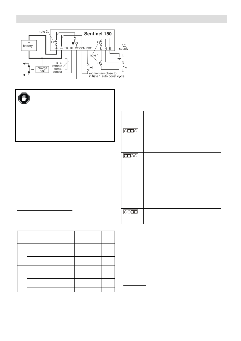
Electrical Connection & Configuration (cont.)
Typical Connection
Notes:
1) AC fusing (F1): see AC Input (power supply) section
2) DC fusing (F2): see DC Output section
3) Battery output is isolated from chassis.
4) Solid state charge fail output relay (UL models only)
shown in de-energised (fault) state.
5) High and low battery volts outputs (UL...NFPA
version) are not shown.
6) AC supply input ground/earth connection:
- CN3 pin 3 on standard (non-UL) models
- M4 chassis stud (marked FG) on UL models