Connecting, Cuewire, Rfbasecue – CUE rfbaseCUE User Manual
Page 6
Advertising
User Manual rfbaseCUE
www.cuesystem.com
Page 6 of 18
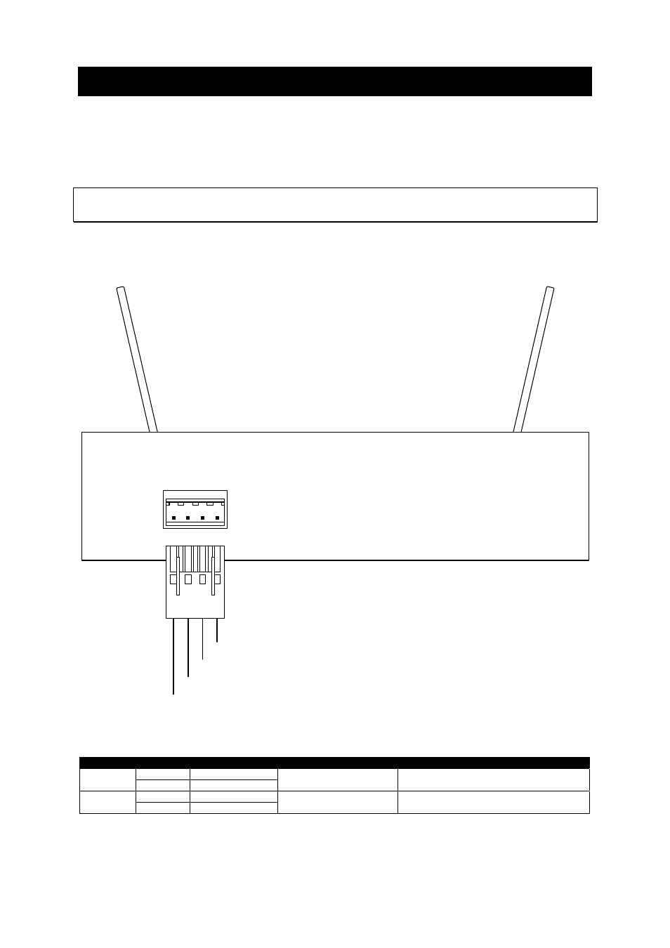
3. Connecting
3.1. CUEwire .....................................................................
The rfbaseCUE needs to be connected to CUEwire (RS-485 and power supply 24 VDC) in the same
way as other control panels.
Important note
There can be only one rfbaseCUE in one control system.
The rear panel is equipped with 4-pin type connector for CUEwire (RS-485 and power supply)
connection. The unit is supplied by 24 VDC (+/-20%), 2 W.
+ - A B
RS 485
rfbaseCUE
B-
A+
Ground
+ 24 VDC
1
4
3
2
The following table describes all CUEwire signals.
Code
Pin nr.
Meaning
Description
Note
1 +24
V
IN
2 Ground
Power input 24 VDC
3 Input/output A+
RS-485
4 Input/output B-
RS-485 RS-485
connection
Advertising