Front panel, Indicators, Antennas – CUE rfbaseCUE User Manual
Page 8: Fuse
User Manual rfbaseCUE
www.cuesystem.com
Page 8 of 18
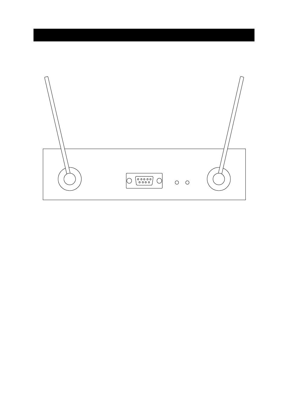
4. Front Panel
4.1. Indicators ..................................................................
LED indicators are located on the front panel of the rfbaseCUE.
AI
AO
HOST
POWER DATA
rfbaseCUE
DATA _________________________This indicator blinks when rfbaseCUE receives or sends valid
RF signals.
POWER _______________________This indicator indicates the presence of feeding voltage.
4.2. Antennas....................................................................
The integral antennas AO and AI are situated on the front panel of rfbaseCUE interface. The whip
antennas are ¼ wave, rotary, non-detachable.
The antennas are to be directed to open air and placed not close to metal pieces.
4.3. Fuse ...........................................................................
The unit is equipped with one resettable fuse rated 0.3 A. There are no serviceable parts inside the
metal case. If the unit is connected to the power, the POWER LED on the front panel lights on.