Z5338 i/o panel, Input, Input link – d&b D80 Touring rack NEMA L21-30 User Manual
Page 10: Remote
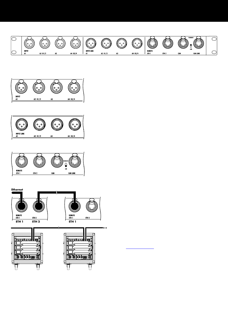
4.1. INPUT
The INPUT section represents the input connectors of the first
amplifier while the other two amplifiers are linked within the rack.
The INPUT section allows both analog and digital audio signals to
be fed to the amplifier.
4.2. INPUT LINK
The INPUT LINK section represents the link output connectors of the
last (third) amplifier and allows the linking of further system racks
using the enclosed rack link cable (Z5333 Rack link).
4.3. REMOTE
The REMOTE section allows the daisy chaining of system racks
within a remote network using the enclosed rack link cable (Z5333
Rack link).
Ethernet network
ETH 1
Represents the upper etherCON connector of the first
amplifier and may be used as input while the other two
amplifiers are linked within the rack.
ETH 2
Represents the bottom etherCON connector of the last
(third) amplifier and may be used as output.
Note: In a daisy chain topology, if one device or an entire
rack fails or is switched off, this also affects all subsequent
devices and/or system racks which are then no longer
connected to the network either.
A detailed description of remote control via Ethernet is given in
the technical information TI 310 (d&b code D5310.EN) which
can be downloaded from the d&b website at
www.dbaudio.com
.
4. Z5338 I/O Panel
d&b Z5330.050 Manual 1.1 en
10