Operation/adjustments, Vertical alignment, Positional adjustment (horizontal position) – d&b Z5147 Rota Clamp User Manual
Page 6: Horizontal alignment
7.
Operation/Adjustments
WARNING!
Carry out positional and directional adjustments one at a
time. Never try to make more than one adjustment
without the others being firmly locked off.
Vertical alignment
CAUTION!
The vertical tilt of the load must not be adjusted by
turning the Rota Clamp against the supporting tube. The
desired total vertical angle is to be set via the holes grid
of the respective adapter or frame in advance as
described above in section 'Assembly'.
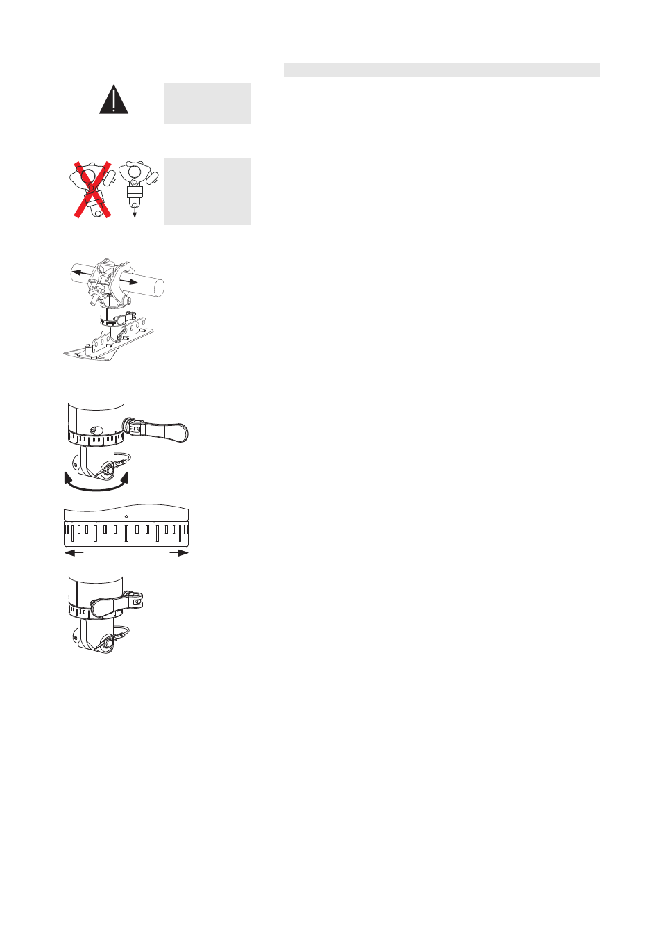
Positional adjustment (Horizontal position)
[2]
Fig. 11: Horizontal position
If an adjustment of the position on the bar is necessary proceed as
follows:
1. Release the locking hand wheel
[2] only enough to release the grip
on the bar.
2. While supporting the weight of the assembly, the positional
adjustment can now be made. Observe that you do not damage the
tube (notching).
3. Always re-tighten the hand wheel after any adjustments.
[3]
0° 10°
10°
20°
20°30° ...
... 30°
Fig. 12: Z5147 Rota Clamp Horizontal
alignment
Horizontal alignment
Horizontal adjustments can be carried out via the rotatable unit of the
clamp. Proceed as follows:
1. Release the excentric lever
[3] of the clamp-
2. Set the desired horizontal angle.
The angle can be read from the scale releated to the mark (point) of
the clamp.
The scale's increment is 10° for every graduation mark. The taller
mark displays an increment of 30°.
3. Close the excentric lever
[3].
Z5147 Mounting instructions
(2.2 EN)
Page 6 of 8