Note on t10 cabinets, Using the flying adapter link – d&b Z5354 E8 User Manual
Page 6
Direction 2
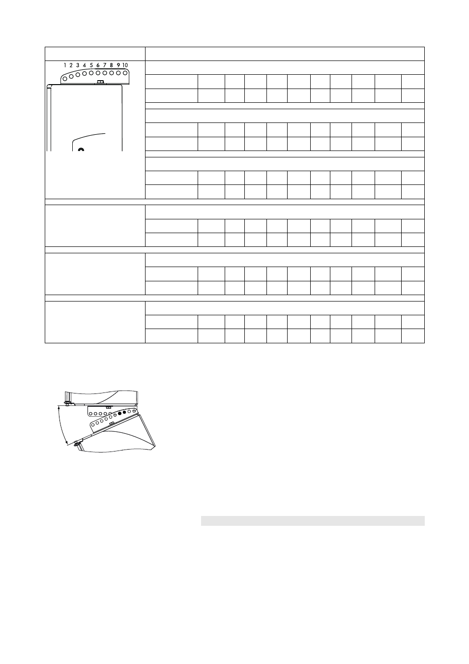
Vertical aiming
E8
Hole grid
1
2
3
4
5
6
7
8
9
10
Angle (°)*
+16
+10
+4
–1
–7
–12
–18
–22
–27
–32
E12 (E12-D)
Hole grid
1
2
3
4
5
6
7
8
9
10
Angle (°)*
0
–3
–6
–10
–13
–17
–20
–24
–27
–30
T10 (in Point Source Mode)
Hole grid
1
2
3
4
5
6
7
8
9
10
Angle (°)*
0
–3
–6
–10
–13
–17
–20
–24
–27
–30
10S/D
Hole grid
1
2
3
4
5
6
7
8
9
10
Angle (°)*
+10.5
+7
+4.5
+1.5
–2.5
–5
–8.5
–11.5
–14.5
–17.5
12S/D
Hole grid
1
2
3
4
5
6
7
8
9
10
Angle (°)*
+15.5
+12
+9
+6
+3.5
+0.5
–3.5
–6
–9.5
–12
Y(i)7P/Y(i)10P
Hole grid
1
2
3
4
5
6
7
8
9
10
Angle (°)*
+14
+10
+6.5
+2.5
+1
–5
–8.5
–12
–15.5
–25
* Positive value: Cabinet points upwards. Negative value: Cabinet points downwards
Note on T10 cabinets
25°
Due to the narrow vertical dispersion angle of 35° of the T10 cabinet in
point source mode, we recommend a maximum splay angle of 25°
between two vertically flown T10 cabinets.
To achieve this, insert the Flying adapter link to hole 7/8 with the Flying
adapter attached in direction 1.
The use of the Flying adapter link is described in the following section 6.
Horizontal aiming
The horizontal aiming of the entire array is adjusted at the suspension
point or lifting device .
6.
Using the Flying adapter link
The Z5355 E8/E12 Flying adapter link enables two Flying adapters to
be linked together. This allows E8, E12 (E12-D), T(i)10 or Y(i)7P/Y(i)10P
cabinets to be arrayed vertically.
The link is equipped with a securing pin (Rue ring cotter) which is
attached to the link by a steel wire. The pin is used to secure the link.
Z5354/Z5355, Mounting instructions
(1.3 EN)
Page 6 of 10