Setup of the assembly – d&b Z5375 T Base plate User Manual
Page 5
Interconnecting the cabinets
The T10 cabinets are interconnected by their Front links on both sides of
the cabinet front and the Splay links on the center rigging strand at the
cabinet's rear.
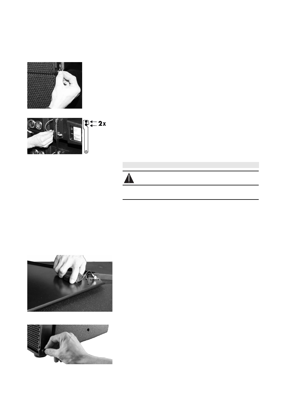
Front links
Once the Front links slide into the respective track of the next cabinet,
the cabinets are interconnected by inserting the Locking pins on both
sides of the cabinet.
Splay links
Fold out the Splay links of the T10 cabinets and hook them into the
preset Locking pins on the rear rigging strand of the next cabinet.
Once the Splay link is hooked in, the second Locking pin must be
inserted. The second Locking pin acts as a "safety pin" to secure the
Splay link from possible hooking off and to fix the set splay angle.
4.
Setup of the assembly
WARNING!
Always secure ground stacked setups against movement and
possible tipping over.
Preparations
- Prepare the cables and link cables according to the number of
amplifier channels and cabinets used.
- Ensure the HF sections of the T10 cabinets to be used are set to Line
source.
1. Prepare the the T Base plate
T10 Groundstack
- Place the T Base plate on the ground.
T10/SUB Groundstack
- Connect the T Base plate with the M20 threaded insert of the
respective subwoofer using the M20 hand bolt.
2. Add the first cabinet
- Release the locking pins on both sides of the cabinet front.
- Attach the cabinet to the T Base plate.
- Insert the Locking pins of the Front links on both sides of the cabinet.
Z5375 Mounting instructions
(1.1 EN)
Page 5 of 8