d&b Z5375 T Base plate User Manual
Page 6
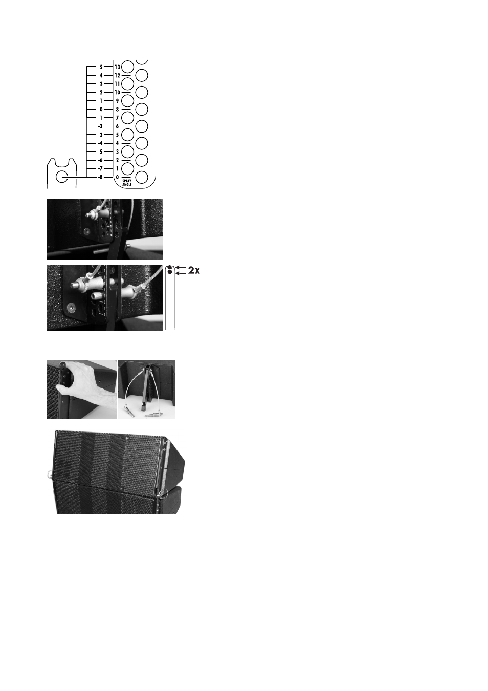
3. Set the angle of the first cabinet
The angle (vertical aiming) of the lowest cabinet can be set in the range
from +5° to –8°. The desired angle is set using the corresponding hole
of the Splay link of the Base plate and the hole grid of the rear rigging
strand of the T10 cabinet. The derived scale is shown in the graphic
opposite.
The notch at the top of the Base plate's Splay link is intended to simplify
the mechanical setup and provides a +2° offset in relation to the hole of
the link.
To set the angle proceed as follows:
- Fold out the Splay link of the cabinet.
- Lift the back of the cabinet
- Insert the first Locking pin into the corresponding hole of the rear
rigging strand of the cabinet.
Example:
To achieve a –5° downtilt of the first cabinet, insert the first Locking
pin (support pin) into the 5° hole of the cabinet.
- Fold up the Base plate's link into the rear rigging strand and lower
the cabinet's back into the notch of the link.
- Insert the second Locking pin (safety pin) into the 3° hole of the
cabinet to secure the link of the Base plate.
4. Add the next cabinet
- Slide out the Front link at bottom cabinet.
- Fold out the Splay link.
- Release the Locking pins on both sides of the cabinet front.
- Attach the cabinet to the first cabinet.
- Insert the Locking pins of the Front links on both sides of the cabinet.
To attach further cabinets, proceed in the same manner.
Z5375 Mounting instructions
(1.1 EN)
Page 6 of 8