d&b Z5385 V Flying adapter User Manual
Page 8
3. Suspend the assembly according to the desired suspension
option.
4. Lift the assembly to a suitable working height.
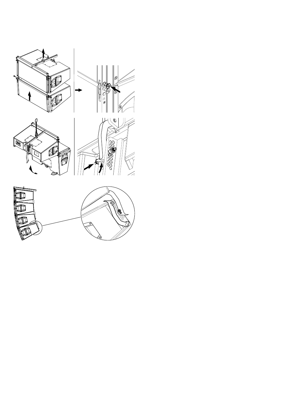
5. Attach the prepared cabinet to the corresponding slots on the
front of the upper cabinet.
6. Insert and lock the second Locking pins of the cabinet's Front
links on both sides.
7. On the rear fold the Splay link of the upper cabinet into the
rigging strand of the bottom cabinet.
8. Raise the bottom cabinet until the hook of the Splay link has
hooked into the preset Locking pin.
9. Release the cabinet and insert the second Locking pin (Safety
pin) to secure the Splay link.
To add further cabinets, proceed in the same manner until the
assembly is completed.
4. Splay link of the last cabinet
The Splay link of the last cabinet can be kept in its park position.
Note: In this case, the lowest cabinet can be set to the
following splay angles: 3°, 5° and 7° to 14°.
5. Rig the cabling
Connect the flying cables and link cables according to the number
of amplifier channels and cabinets used.
6. Check the assembly
Before hoisting the array to its operating position recheck the
actual status of the entire assembly.
–
Check the attachment of the shackles or Rota clamp to the
Flying adapter.
–
Check the attachment of the Flying adapter to the first cabinet
and ensure all Locking pins are properly inserted and locked.
–
Check all Front links on both sides of the cabinets and ensure
all Locking pins are properly inserted and locked.
–
Check the splay angle settings and the Splay links on the rear
of the cabinets and ensure all Locking pins are properly
inserted and locked.
–
In "Single pick point operation" check the desired total vertical
aiming of the entire array using an inclinometer.
d&b Z5385 V Flying adapter, Rigging manual (1.3 EN)
8