Gen-locking cables on h-link and s-link boards – Datapath VSN890 User Manual
Page 13
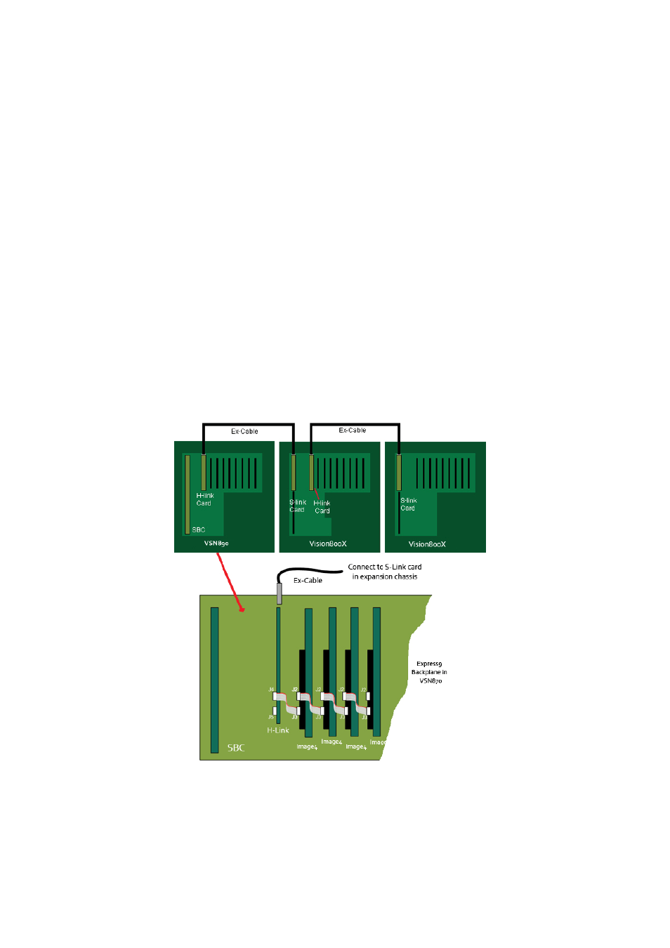
When connecting a Vision800X expansion chassis to a VSN890 machine the H-Link card in the VSN890
must be installed into the x8 slot. The S-Link card in the Vision800X should be installed in the PICMG1.3
SBC slot.
Connect the H-Link and S-Link cards using the Ex-Cable as shown in the illustrations on the previous page.
Gen-locking Cables on H-Link and S-Link Boards
Connectors J4 and J5 are used for Gen-locking multiple chassis together. This is useful when using multi-
ple chassis that each contains a number of Datapath Image4 graphics cards. The gen-locking chain can be
used to tie the outputs of the graphics cards together so that they all render their outputs to the screen
at the same time. This makes fast moving images appear smoother on the video/data wall and eliminates
‘tearing’ artefacts on the display.
To create a gen-locked chain using the H-Link and corresponding S-Link cards, firstly ensure that the
system is powered down. Then connect the gen-locked output of the closest Image4 graphics card to con-
nector J4 (GEN LOCK IN) on the H-Link board using the cable supplied with your H-Link board, as shown in
the picture below. Note that this cable is longer than the cable supplied with each Image4 graphics card in
order to cover the extra distance between the Image4 and the H-Link board. This will send the gen-locked
clock over the Ex-cable to the next downstream chassis.
In order to complete the gen-locked link, you will need to connect the output of the S-Link board in the
downstream expansion chassis back into the next Image4 graphics card in the chain, as per the following
image. Note again that the cable supplied with the S-Link board is longer than those supplied with the
Image4 graphics card in order to cover the extra distance.
13
Fig.12