Proper alignment of the loudspeakers, Wiring, Terminal assignment – KLING & FREITAG K&F SONA 8 User Manual
Page 13: Wiring diagrams, Wiring instructions, 1 terminal assignment, 2 wiring diagrams
User's manual
K&F SONA 8
KLING & FREITAG GMBH © 2014
Version 1.1
Page 13 of 21
5.
Make sure that the stand pole in
the stand adapter reaches up to
behind the clamp screw.
Tighten the clamping screw.
The speaker is now securely
connected to the stand. Now adjust
the speaker.
6.
Proper Alignment of the Loudspeakers
Please note that precisely targeted speaker systems can significantly improve the acoustic
result. It is not possible to make generalities about the alignment of specific systems because
the room has a substantial influence on the signal and the audible result.
As a rule, the mid- and high-transducers of loudspeakers should be mounted above the
audience's face value, so that the sound distribution cannot be shadowed.
In many cases it is advisable to mount a loudspeaker higher, so that the sound will be
distributed throughout the room more evenly. Low standing systems result in a greater
difference in volume between front and back seats than higher standing systems.
To simulate the correct alignment of the speakers beforehand, there are various programs
such as ‘EASE’ or ‘Ulysses’. On the homepage www.kling-freitag.de, KLING & FREITAG
provides the simulation data for the speakers to be downloaded.
7.
Wiring
Warning
Electrical current of loudspeaker signal may be hazardous for the human body.
Always make sure the connectors secured against touch when the equipment is in use.
Always fully insert bared wire ends into the push connector or the Phoenix plug such that
bared parts of wire can not be touched.
For speakers with Phoenix connector the bared wire ends have to be accurately screwed into
the plugs.
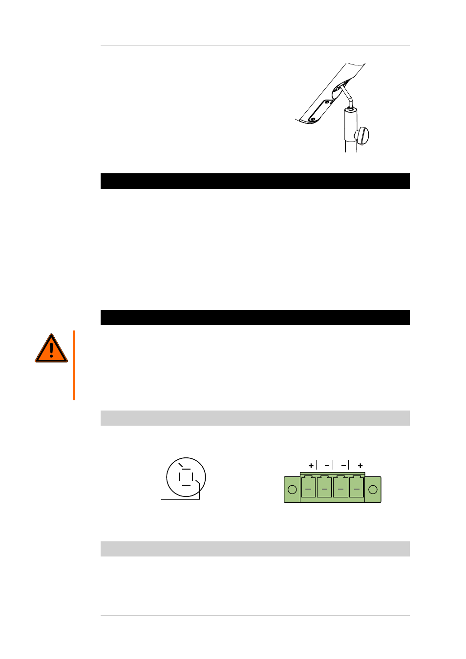
7.1
Terminal assignment
Speakon connector
Phoenix connector
-
1
-
2
-
1+
2+
+
IN
1
1
1
1
Pin 1 is parallel at all connections.
7.2
Wiring Diagrams
You will find all necessary pin diagrams for operations with the CD 44 Controller in the User’s
Manual of the CD 44! This applies for use with and without the K&F Subwoofer.