4 instructions for versions with ‚100 v' option, 2 connecting diagram of the 100v speaker inputs, 5 instructions for suspending the speakers – KLING & FREITAG K&F CA 106 User Manual
Page 8: Instructions for versions with ‘100 v’ option, Connecting diagram of the 100v speaker inputs, Instructions for suspending the speakers
User's Manual
CA 106
KLING & FREITAG GMBH ©1995 - 2006
Version 5.1, 09.11.2006
Page 8 of 26
4.
Instructions for Versions with ‘100 V’ Option
Kling & Freitag speakers are fitted with high-quality toroidal transformers. This serves to
minimize loss of sound. Highly professional sound reinforcement results can be achieved
using 100 V Kling & Freitag speakers.
4.1
Reasons for choosing Speakers with 100 V Technology
− Reduction in conduction loss.
− Easy assembly of a loudspeaker network due to simple parallel wiring.
The sum of the output power of the individual speakers (stated as VA = W)
must not exceed the output power of the 100 V amplifier.
− Speakers are galvanically isolated.
− Speakers can be integrated into existing 100 V systems.
4.2
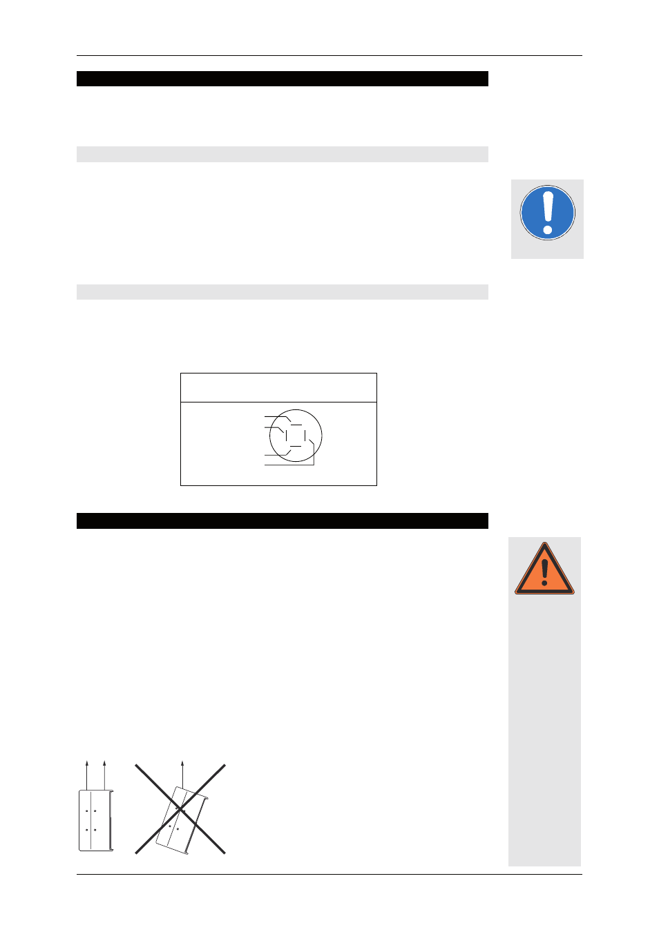
Connecting Diagram of the 100V Speaker Inputs
The 100 V transformer for the CA 106 has 3 taps. These enable the speaker to be oper-
ated at 50 VA, 100 VA or 150 VA. Which tap is connected to which pin can be seen
below.
150VA transformer with taps for 50VA,
100VA and 150VA
IN
1
-
2
-
1
+
2
+
50VA
100VA
150VA
0
all pins parallel to out
5.
Instructions for Suspending the Speakers
The speakers may only be suspended by trained specialised personnel.
Please follow the accompanying safety and assembly instructions carefully as
well as the required safety factors. Pay attention to the corresponding national
safety regulations.
Speaker systems, whether single or connected to one another, must always be secured
to a second separate point.
Ensure that all connections are secured to prevent their detaching on their own and that
only admissible statically tested and sufficiently sized connecting devices, ropes and
chains are used.
The M6 threads may only be used in combination with the speaker mount ‘Omnimount
50’.
A maximum load of 10 kg may be suspended from the two flying points (M8 thread
inserts) of one Speaker. This means a maximum additional load of 5 kg on each
flying point.
Important
Warning