Locations of the jumpers and connectors, Top view, Chapter 2: jumpers and connectors – NEXCOM NISE 103 User Manual
Page 22
Advertising
Copyright © 2011 NEXCOM International Co., Ltd. All Rights Reserved.
9
Chapter 2: Jumpers and Connectors
NISE 103 User Manual
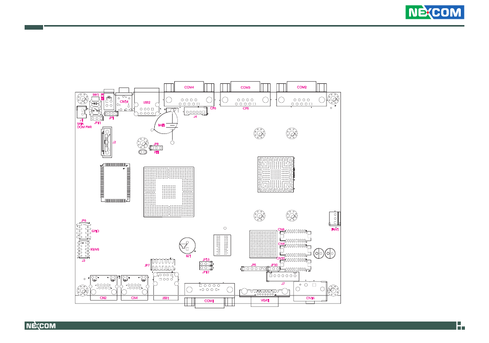
Locations of the Jumpers and Connectors
The figure below is the NISB 103 main board which is used in the NISE 103 system. It shows the locations of the jumpers and connectors.
12
VGA1
14
3
5
10
1
6
8
11
15
1
2
CN16
1
2
19
20
CN8
1
2
19
20
CN9
1
2
19
20
CN10
1
7
J2
BZ1
BAT1
LED1
CN14
5
2
6
1
3
4
SW1
1
J1
RT1
1
7
8
2
9
10
11
12
CN2
1
7
8
2
9
10
11
12
CN4
5
1
4
USB2
8
5
1
4
USB1
1
5
6
9
COM4
1
5
6
9
COM2
5
6
9
COM3
1
5
6
9
COM1
1
6
J4
7
1
J7
3
1
FAN1
H7
6
1
JP5
1
JP12
1
JP13
1
JP11
1
JP8
3
1
JP10
4
1
JP1
A
103
102
65
64
1
JP6
2
8
7
1
U11
1
14
13
JP7
2
1
10
9
J3
21
19
18
16
14
13
12
11
10
9
8
7
5
4
3
2
1
29
FB22
CP6
CP5
SATA
DOM PWR
KB/MS
GPIO
Top View
Advertising