Appendix b: digital i/o programming guide – NEXCOM APPC 1230T User Manual
Page 124
Copyright © 2012 NEXCOM International Co., Ltd. All Rights Reserved.
108
APPC 1230T/1231T/1235T/1530T/1531T/1730T/1731T/1930T/1931T User Manual
Appendix B: Digital I/O Programming Guide
Appendix B: Digital I/O Programming Guide
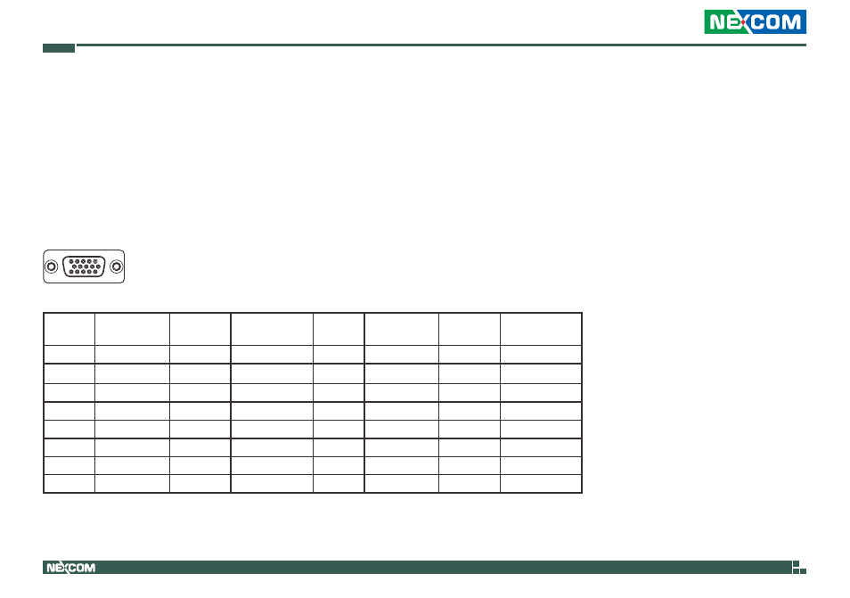
Digital I/O (Digital Input/Output) pins are provided for custom system
design. This appendix provides definitions and its default setting for the
fifteen Digital I/O pins in the APPC series. The pin definition is shown in the
following table:
Pin
GPI/O mode PowerOn
Default
Address
Pin
GPI/O mode PowerOn
Default
Address
1
DI1
High
A05h (bit0)
2
DI2
High
A05h (bit1)
3
DI3
High
A05h (bit2)
4
DI4
High
A05h (bit3)
5
GND
-
-
6
COM
-
-
7
NC
-
-
8
NC
-
-
9
DO1
Low
A05h (bit4)
10
DO2
Low
A05h (bit5)
11
DO3
Low
A05h (bit6)
12
DO4
Low
A01h (bit7)
13
GND
-
-
14
GND
-
-
15
GND
-
-
Control the DO pin (9/10/11/12) level from I/O port A05h bit (4/5/6) and A01h bit (7).
The bit is Set/Clear indicated output High/Low
1
5
11
15