Locations of the jumpers and connectors, Mainboard – NEXCOM VMC 100 User Manual
Page 36
Advertising
Copyright © 2014 NEXCOM International Co., Ltd. All rights reserved
22
VMC 100/1100 Series User Manual
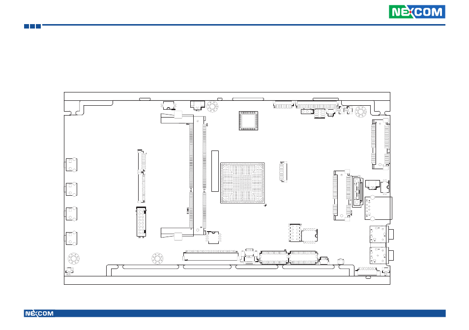
Chapter 3: Jumpers and Connectors
Locations of the Jumpers and Connectors
The figure below is the mainboard used in the VMC system. It shows the locations of the jumpers and connectors.
J2
J1
JP1
SW1
SW3
JP2
CN3
SW6
SW7
J9
J8
J6
Mainboard
Advertising
This manual is related to the following products: