Pir-88m set-up, Caution – Oxmoor PIR-88M User Manual
Page 6
Page 4
PIR-88M SET-UP
PIR-88M SET-UP OVERVIEW
The PIR-88M has three sets of internal jumpers and one dip
switch. The interinal jumpers are used to configure carrier
frequency, output impedance and output drive levels. The dip
switch is used to set the PA-422 address.
The factory settings are:
Carrier frequency =
95 kHz
Output Impedance = 5O ohm
Output Drive Level = 750 V rms
PA-422 address =
3
If it is necessary to make changes to the factory settings, please
follow the directions below:
Figure 2.3: Factory Set-Up for PA-422 Address 3
SW1 PA-422 SET-UP PROCEDURE
(Refer to Figure 2.3)
Switch SW1 determines the PA-422 address. Note: unit must
be reset after PA-422 address change.
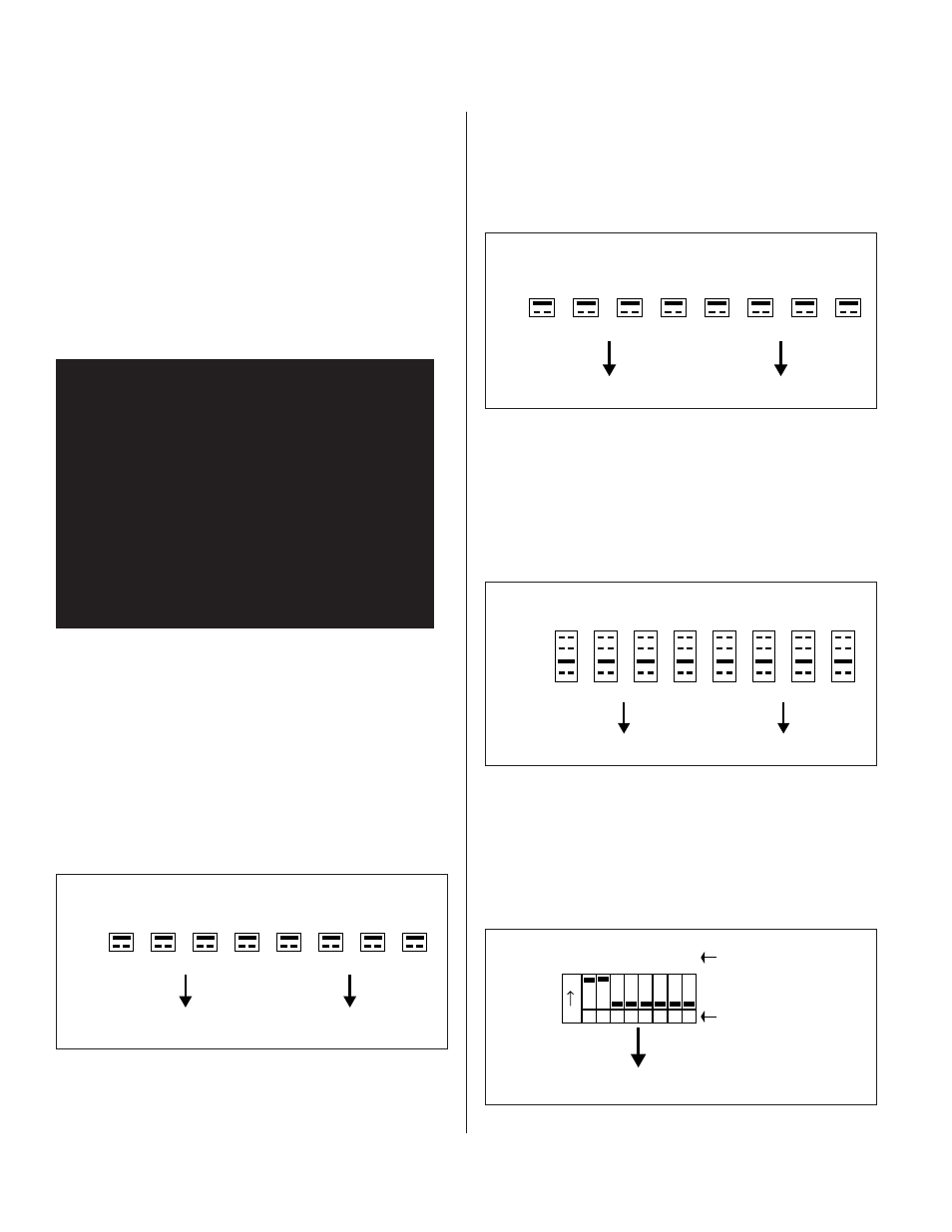
Figure 2.0: Factory Set-Up for 95 kHz
ACCESS TO INTERNAL JUMPERS:
1. Disconnect the external AC power adaptor.
2. Remove the top cover screws and set the cover aside.
PIR-88M CARRIER FREQUENCY SELECTION:
(Refer to Figure 2.0)
The carrier frequency jumpers are located right behind the
front panel carrier frequency LED indicators. The set of pins
closest to the front panel are the 95 kHz setting.
95 khz
J16
CH: 1
J15
CH: 2
J12
CH: 3
J11
CH: 4
J8
CH: 5
J7
CH: 6
J4
CH: 7
J2
CH: 8
Carrier Frequency Jumpers
250 kHz
PIR-88M RF OUTPUT IMPEDANCE SELECTION:
(Refer to Figure 2.1)
The output impedance jumpers are located behind the rear
panel BNC RF jacks. The set of pins closest to the rear panel is
the 50 ohm settings.
Arrows Pointing To REAR Panel Of PIR-88M
75 ohm
J17
CH: 8
J18
CH: 7
J19
CH: 6
J20
CH: 5
J21
CH: 4
J22
CH: 3
J23
CH: 2
J24
CH: 1
Output Impedance Selection
50 ohm
Arrows Pointing To REAR Panel Of PIR-88M
Figure 2.1: Factory Set-Up for 50 ohm output
SW1
PA-422 Address
Switch Number
ON
1 2 3 4 5 6 7 8
1
2
4
8
16
32
64
128
Arrow Pointing To FRONT Panel Of PIR-88M
0 - 2.0 V rms
1.5 V rms
750 V rms
400 V rms
JP1
CH: 8
JP2
CH: 7
JP3
CH: 6
JP4
CH: 5
JP5
CH: 4
JP6
CH: 3
JP7
CH: 2
JP8
CH: 1
Output Level Jumpers
OUTPUT LEVEL SET-UP PROCEDURE
(Refer to Figure 2.2)
JP1 through JP8 determines the drive level of each terminated
output.
Figure 2.2: Factory Set-Up for 750 V rms terminated output
Arrows Pointing To REAR Panel Of PIR-88M
CAUTION!
Hazardous voltages are present
inside the chassis. Before
opening the case to gain access
to the printed circuit board,
always remove the AC power from
the unit by disconnecting the
external AC power adaptor.