Rmx-44 callouts – Oxmoor RMX-44 User Manual
Page 4
Page 2
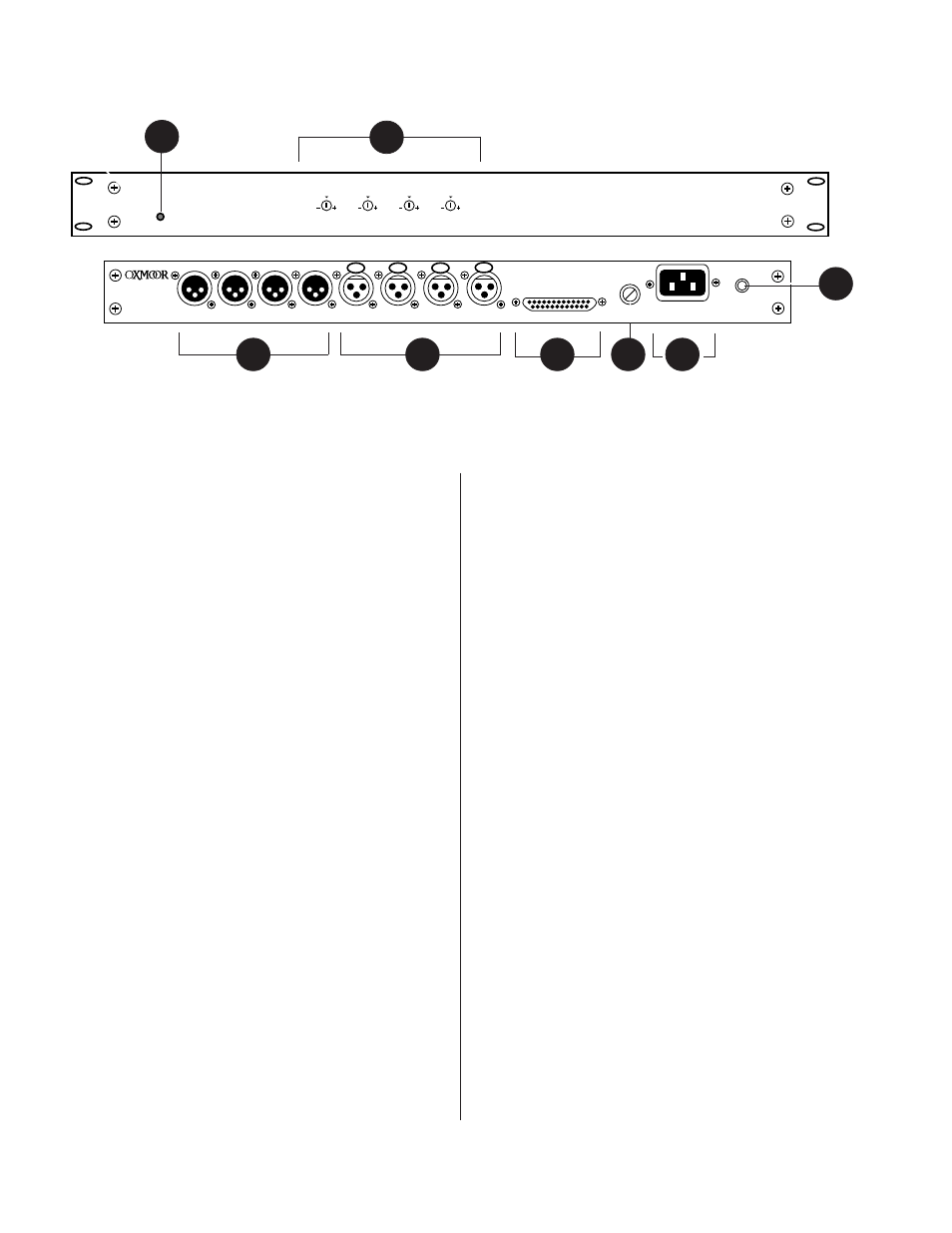
Figure 1.1: Front and Rear Panel Views of RMX-44
RMX-44 CALLOUTS
(Callouts refer to Figures 1.1, 1.2, and 1.3)
1. POWER LED
- The front panel LED is illuminated
when the unit is on. The absence of an On/Off
switch is a performance safety feature, eliminating
accidental shutdown during operation.
2. INPUT CONNECTORS
- XLR inputs, Pin 2 positive,
accept balanced or unbalanced signals from line-
level devices.
3. INPUT STAGE
- The RF-suppressed input circuit is
electronically balanced (differential), and capable
of handling a maximum signal level of +24 dBu.
Balanced input impedance is approximately 80k
ohms, with a nominal input level range of -10 to
+8 dBu.
4. INPUT GAIN TRIM POTS
- (labelled "INPUT 1,"
"INPUT 2,” etc.) Accessed through the front panel
with a small flat-blade screwdriver, these trim
pots adjust the input stage gain +/-15 dB, to
compensate for varying input signal levels.
5. OUTPUT STAGE
- The output stage is electronically
balanced (push-pull) and AC coupled. Output
impedance is approximately 150 ohms. Each
output can provide a maximum level of +24 dBm
into a 600 ohm load, or +26 dBu unterminated.
6. BALANCED/UNBALANCED JUMPER BLOCKS
-
These permit each output to be unbalanced
independently, if necessary (see SET-UP).
OXMOOR
RMX-44 MIXING MATRIX
POWER
INPUT 1
INPUT 2
INPUT 3
INPUT 4
PIN 2 POSITIVE ON ALL
AUDIO CONNECTIONS
CONTROL PORT
FUSE
POWER
CHASSIS
SERIAL NUMBER
OUTPUT D
OUTPUT C
OUTPUT B
OUTPUT A
INPUT 4
INPUT 3
INPUT 2
INPUT 1
2
7
8
9
10
4
11
1
4
9
10
11
8
2
7. OUTPUT CONNECTORS
- XLR outputs, pin 2
positive, accommodate balanced or unbalanced
lines.
8. CONTROL PORT CONNECTOR
- Female, 25-pin,
standard D-sub connector. Provides contacts for
jumpers or external switching to assign routing
of inputs to outputs. Latching contact closures
required (see SET-UP). Additional contacts
provide system mute capability and +15 VDC, 50
mA, output for powering LEDs, etc.
9. CHASSIS GROUND POST
- Nuts on a threaded
stud enable the installer to conveniently secure a
ground wire to the chassis.
10. POWER CONNECTOR
- Standard IEC 3-pin
connector for AC power cord. Use only with
grounded (3-wire) outlets. Cord sets are available
for all world connection standards.
11. FUSE HOLDER
- Replace only with approved
type of fuse in a rating appropriate to the mains
voltage, as indicated on back panel (see
SPECIFICATIONS).
9
7