Rmx-44 & rmx-62 set-up – Oxmoor RMX-44 User Manual
Page 8
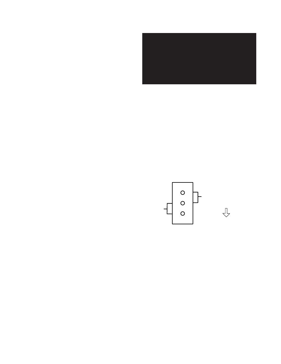
UNBALANCED
BALANCED
Rear
of
Chassis
Page 6
RMX-44 & RMX-62 SET-UP
Also, output connections are simplified by allow-
ing the use of standard cables in all cases.
THE PROCEDURE:
1. Gain access to the inside of the chassis.
a. Disconnect the power cord.
b. Remove the four screws that secure the
top cover and set the cover aside with the
screws.
2. Locate the Balanced/Unbalanced Jumper Block
next to the connector for the output you wish to
reconfigure. These are called out on Figures 1.3
The RMX-44 and RMX-62 may easily be configured
to meet your specific requirements. You may make
changes to the factory configuration of the unit in
two areas: outputs and inputs.
Each output has been configured at the factory to
be balanced. You may change each output indepen-
dently to be unbalanced. This is the only set-up pro-
cedure that requires access to the chassis interior.
NOTE: If your unit has transformer coupled out-
puts (i.e., models RMX-44T or RMX-62T) no modi-
fication is required for unbalanced operation.
Each input may be assigned to any output or com-
bination of outputs. Multiple inputs may also be
routed to each output.
CONVERTING OUTPUTS FROM BALANCED TO
UNBALANCED
(ELECTRONICALLY BALANCED
OUTPUTS)
Each output is provided with an internal jumper;
the position of each jumper determines whether its
associated output is balanced (push-pull) or unbal-
anced. All outputs are balanced as delivered from
the factory. In the unbalanced configuration, pin 3
of the output connector is grounded, and the maxi-
mum output level drops by 6 dB.
If you wish to operate one or more of the outputs
unbalanced, you must follow this procedure. Set-
ting the internal jumper correctly provides two ben-
efits.
First, the possibility of shorting the corresponding
output driver to ground is eliminated. While an
output short will not harm the circuit, it may result
in increased distortion and crosstalk.
CAUTION:
Hazardous voltages are present inside
the chassis. Before opening the case to
gain access to the Balanced/Unbalanced
Jumpers, always remove the power from
the unit by disconnecting the AC cord.
and 2.3.) The jumper is factory installed in the
balanced position.
3. Observing the positions shown in Figure 3.1 (and
marked on the circuit board), remove the jumper
and reinstall it in the unbalanced position.
4. Replace top cover and screws.
CONNECTOR WIRING FOR UNBALANCED
OUTPUT:
UNBALANCED
Pin 2 = "HOT"
Pin 3 = "COMMON"
Pin 1 = "SHIELD
Figure 3.1: Typical Balanced/Unbalanced Jumper Block