Introduction, Operation, Product overview – Televes DigiSlot DVB-T modulator, wall mount User Manual
Page 8: Blocks diagram, Technical specifi cations installation precautions, General precautions, Power precautions, Grounding requirement, Button introduction
8
DVB-T modulator
Introduction
Product overview
The product is presented for two types of mounting: onto the wall (Ref. 554511),
and 19 inch cabinet mounting (Ref. 554611).
The modulator converts the HD A/V baseband signals into a DVB-T multiplex of
RF within the range 47 ~ 862 MHz.
It features 2 encoders and 1 additional RF input. The input signals of the
encoders can come from satellite receivers, CCTV cameras, Blu-ray players,
antennas, ... etc. Its output is a DVB-T TV multiplex which can be received with
the corresponding DTT STB.
The device can be used for monitoring, training courses and presentations,
schools, universities, hospitals, ..., in addition to being the best choice for public
premises which off er sporting events, VIP entertainment channels,.. and other.
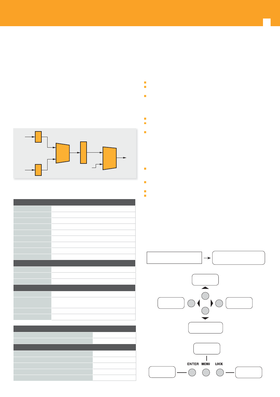
Blocks diagram
A/V in
Encoder
MUX
Modulator
Mix
RF in
RF out
A/V in
Encoder
Technical specifi cations
Installation precautions
This section to explain the cautions the users must have to avoid any injures
when using or installing the product. For this reason, please read all details here
before installing or using the product.
General Precautions
Must be operated and maintained free of dust or dirty.
The cover should be securely fastened, do not open the cover of the products
with the power on.
After use, securely stow away all loose cables, external antenna, and others.
Power precautions
When you connect the power source, make sure it will not cause any overload.
Avoid operating on a wet fl oor in the open. Make sure the extension cable is
in good condition.
Make sure the power switch is off before you start to install the device.
Grounding Requirement
All function modules’ good grounding is the basis of reliability and stability of
devices. Also, they are the most important guarantee of lightning arresting and
interference rejection. Therefore, the system must follow this rule.
Grounding conductor must be a copper conductor in order to reduce high
frequency impedance, and the grounding wire must be as thick and short as
possible.
Users should make sure the both ends of grounding wire are electric
conductor and antirust.
It is prohibited to use any other device as part of grounding electric circuit.
The area of the conduction between grounding wire and device’s frame
should be no less than 2.5mm
2
Operation
Button introduction
LCD display window.
Display window for setting menu
Status display when power On.
DVB-T XXX.00MHz
X.XXMbps 0.0M
Setting value up
and moving up
To move left
To move right
Setting value down
and moving down
Back step
Confi rm setting
Lock button
DVB-T modulator section
Standard
EN300744
FFT mode
2K, 8K
Bandwidth
6M, 7M, 8M
Constellation
QPSK, 16QAM, 64QAM
Guard Interval
1/4, 1/8, 1/16, 1/32
FEC
1/2, 2/3, 3/4, 5/6, 7/8
MER
≥42dB
RF frequency
47~862MHz, 1KHz step
RF output level
-30~ -10dBm (81~97 dBμV), 0.1dB step
Interface
Front panel
buttons, LCD display
Remote manag.
Web NMS
Language
English
General
Mains
AC 100V~240V
Dimensions
360 x 280 x 50 mm (554511)
480 x 300 x 44 mm 1U rack 19” ( 554611)
Weight
2.6 kgs
Operating temp.
0~45 ºC
Confi gurations
LCN confi g
Yes
NIT Table confi g
Yes
Settings
Network Name
Yes
Network ID
Yes
Transport Stream ID (TSID)
Yes
Original Network ID (ONID)
Yes
Hierarchy Information
Yes