Televes DigiSlot DVB-T modulator, wall mount User Manual
Page 9
9
EN
DVB-T modulator
Initial Status
Switch On, then below status will be displayed, few seconds’ initialization then
open startup picture
Start up ...
Start OK ...
DVB-T XXX.00MHz
X.XXMbps Y.YYMbps
DVB-T: indicate the modulation standard of this device
XXX.XX MHz: indicate the output frequency, and the frequency range is
47~862MHz
X.XX Mbps: indicate the encoding bit rate in slot 1
Y.YY Mbps: indicate the encoding bit rate in slot 2
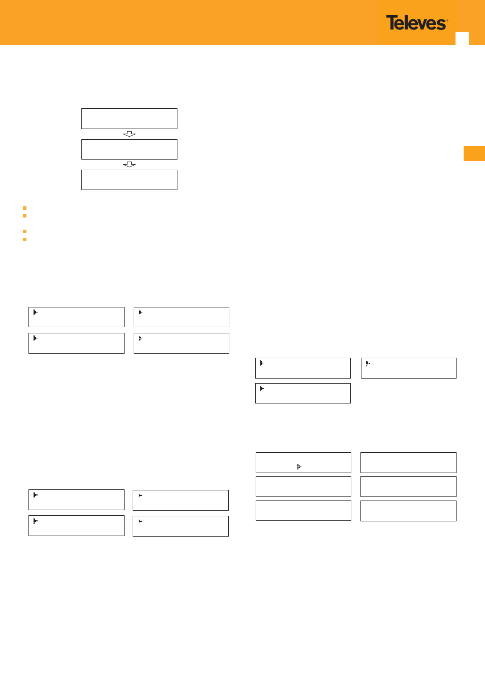
General setting for Main Menu
By pressing “Lock” key to enter the main menu, the LCD will display the
following pages:
1 Alarm Status
2 Encode Setting
3 Modulate Setting
4 IP Output Setting
5 Network Setting
6 Saving Config
7 Loading Config
8 Version
User pressing UP or DOWN buttons to specifi ed menu item, and then pressing
ENTER to enter the submenus as below:
1) Alarm status --- the alarm indicator will light on if there is no A/V signals
input.
2) Encoder setting --- choose this submenu, the LCD will show “input setting”,
press the ENTER key and control the UP or Down key to move the arrow.
User could fi nd how to set the audio and video encoding bit rate.
3) Modulator setting
When the “modulator setting” submenu has been chosen, users can fi nd below
diff erent parameters for setting. And the LCD window would respectively show
like these.
3.1 Bandwidth
3.2 Constellation
3.3 Transmisson Mod
3.4 Guard Interval
3.5 Code Rate
3.6 RF Frequency
3.7 RF Outlevel
3.1- Bandwidth
There are three possible options provided for selecting bandwidth: 6M, 7M, and
8M. When the display shows them, user just need swift LEFT and RIGHT key to
choose and repressing “ENTER” for confi rm.
3.2- Constellation
Three diff erent constellations: QPSK, 16QAM, and 64QAM will be show on the
LCD window when Constellation been entered.
- QPSK: Quadrature Phase Shift Keying, Selecting this option indicates the
device works as DVB-S modulation mode
- 16QAM: Quadrature Amplitude Modulation is 16
- 64QAM: Quadrature Amplitude Modulation is 64
Setting method just the same, when the display shows them, user just need
swift LEFT and RIGHT key to choose and repressing “ENTER” for confi rm.
3.3- Transmission mode
After entering Trans mode, the LCD would show the current working mode.
User can move LEFT/RIGHT key and repress ENTER key to select and confi rm.
2K and 8K are the options.
- 2K: when the device works as current mode, the number of current carrier
is 2048.
- 8K: when the device works as current mode, the number of current carrier
is 8192.
3.4- Guard interval
In communications, guard intervals are used to ensure that distinct transmissions
do not interfere with one another. These transmissions may belong to diff erent
operators (as in TDMA) or same operator (as in OFDM).
The purpose of the guard interval is to introduce immunity to propagation
delays, echoes and refl ections, to which digital data is normally very sensitive.
There are four possible options provided to be selected. They are 1/4, 1/8, 1/16,
1/32. User can shift the LEFT/RIGHT key to select and press ENTER to confi rm.
3.5- FEC
Forward Error Correction (FEC) rates include 1/2, 2/3, 3/4, 5/6, and 7/8. After
entering FEC submenu, and the LCD display would shows them, users just need
press LEFT and RIGHT button to choose, and press ENTER button for confi rm.
3.6- RF Frequency
The RF output frequency range is from 30 to 1000MHz with 1K stepping. After
entering the RF frequency setting submenu, users the can press LEFT, RIGHT,
UP, and DOWN buttons to adjust the frequency and confi rm by press ENTER
button.
3.7- RF out level
The RF attenuation range is from -30~-10dBm (81~97dBμV) with 0.1dB step.
After entering this setting submenu, user can shift UP/DOWN/LEFT/RIGHT key
to set the output level and press ENTER to confi rm.
4) IP Output Setting
4.1 IP Output
4.2 Service IP
4.3 Output IP
4.4 Subnet Mask
4.5 Gateway
4.6 Port
User can press “UP/DOWN” to choose this item. “Enter” and “LEFT/RIGHT” to
set the parameters.
If not set the following parameters will be no use, the IP Output will not work.
IP Output
OFF ON
Service IP
192.168.002.137
Output IP
224.002.002.002
Subnet Mask
255.255.255.000
Gateway
192.168.002.000
Port
01234
4.1- IP Output
The IP Output option, must be enable.
4.2- Service IP
The IP Output Port address. The format is xxx.xxx.xxx.xxx (like as 192.168.2.137).
4.3- Output IP
The IP Output data receive address. The format is xxx.xxx.xxx.xxx (like as
224.2.2.2). After set the Output IP address , you must use the new address to
receive IP Output data.
4.4- Subnet Mask
General is 255.255.255.0, it is must the same in a local area network.
4.5- Gateway
If the device is in diff erent net segment, you must set the gateway.