ThunderMax PN#309-362 - FL Touring Models User Manual
Page 3
www.Thunder-Max.com
309-362 Installation / Setup Guide V2013.10.15
3
ECM. Before installing connector, lightly spread some
dielectric grease on harness connector terminals, and on
the inside lip of the connector port opening of the ECM
to allow the rubber weather seal in the connector plug to
slide into place without binding. Apply a dab of grease
to the (2) upper and lower locating pins on the
ThunderMax housing as well (arrows).
See ‘Tips’ on
page 7 for additional dielectric grease instructions.
Before connecting, verify that the locking bar is in the
fully open, rearward position (locking bar index pin is
fully engaged with rear notch in the socket housing).
Important Note: If socket housing with grounding pin
are not properly aligned during connector installation
damage to the grounding pin will likely occur, which will
require you to return the ThunderMax ECM for repair to
the damaged pin.
Rotate the locking bar forward to engage the connector.
Observe that the colored cam locks are moving with the
locking bar; proper execution will show both colored cam
locks visible in equal amounts on the forward-facing side
of the connector when the locking bar is in its fully
seated position with the button lock engaged, as in the
image below (do not force the locking bar). Index pin
will engage front notch in socket housing.
Important Note: Pin and socket housing of the
connector must be fully engaged before you rotate the
locking bar to the forward position. Forcing the locking
bar forward before the connector is fully engaged will
damage the connector and/or the ECM
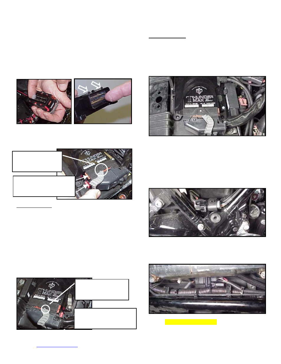
FL-K:
Place the ThunderMax ECM into the ECM caddy.
If equipped, position alarm antenna as shown.
FL-L:
Connect the oxygen sensor harnesses to the
AutoTune harness. Carefully wire tie the leads to the
motorcycle. Take extra care to ensure harness and
sensor leads are safe from rubbing or chaffing on the
motorcycle. Use all supplied wire ties; add extra ties if
needed to properly secure wiring on your installation.
FL-M:
Position the rear connector under the ABS caddy
and attach with wire ties provided as shown.
FL-N:
Position front connector above lower frame rail
between engine and transmission. Attach to existing
harness with provided wire ties. Inspect all wiring to
make sure it is clear of moving parts and excessive heat.
FL-O:
Re-install the ECM fuse and replace the side
covers.
Fully closed position:
Index pin engaged
with forward notch
Sliding colored cam locks
in fully open position
towards rear of bike
Sliding colored cam locks
in fully closed position
towards front of bike
Fully open position:
Index pin engaged
with rearward notch