5installation, Figure 1 figure 2, Floor protection figure 4 – United States Stove Company 5040 User Manual
Page 7: Alcove clearances
5
INSTALLATION
SPECIFICATIONS
FREESTANDING:
Width: 21 ½”
Height: 28 ½” (with legs or pedestal)
Depth: 24”
Weight: 185 lbs.
Pedestal: 40 lbs.
Legs: 13 lbs.
Flue size: 3” or 4”
Hopper Capacity: Up to 45 lbs.
(this can vary widely depending on pellet size, length, and diameter)
EPA status: exempt
Burn time: 1 lb. to 4 ½ lbs. per hour
BTU range: 8,200 to 40,000
Approved installations: mobile home, alcove, conventional
PREPARATION
Factory packaging must be removed, and some minor assembly work
is required prior to installation. Access to the rear of the stove is nec-
essary.
The circuit board/control panel must be unpacked and installed in the
side flashing on the insert or side panel on the freestanding. (See
installation instructions provided with the circuit board)
NOTE: Normally, your dealer will perform these functions.
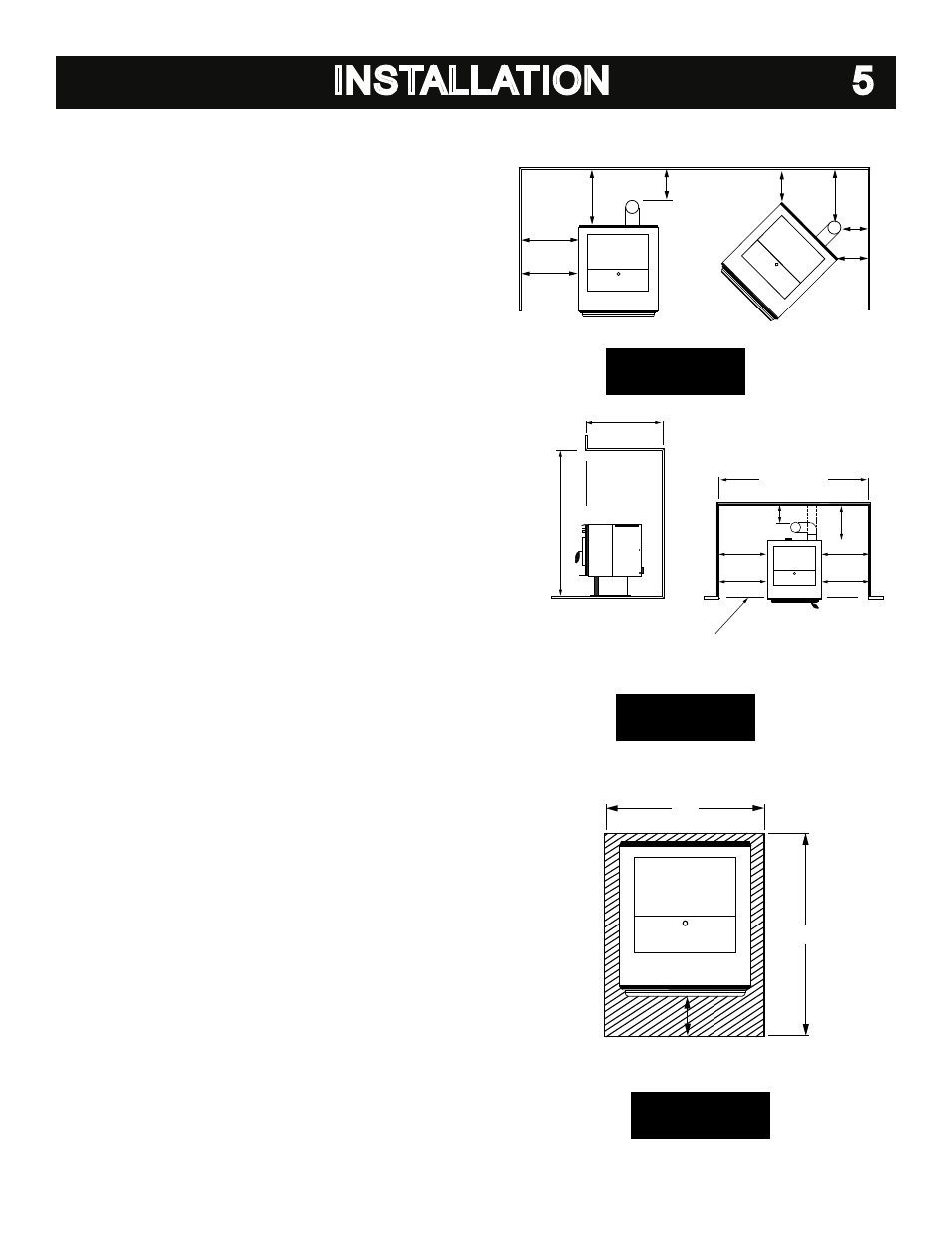
CLEARANCES
This freestanding appliance has been tested and listed for installation
in residential, mobile home and alcove applications.
FLOOR PROTECTION: Freestanding installations, minimum 21” wide
by 28” deep. The stove must be placed on a continuous (grouted
joints) noncombustible material such as ceramic tile, cement board,
brick, 3/8” millboard or equivalent, or other approved or listed material
suited for floor protection.
THE MATERIAL(S) USED MUST HAVE, OR COMBINE TO HAVE, A
MINIMUM INSULATIVE RATING OF ‘R1’.
NOTE: ceramic tile, or any tile, requires a continuous sheet beneath
to prevent the possibility of embers falling through to the combustible
floor if cracks or separation should occur in the finished surface, this
would include floor protection for Built-in raised hearths. Check local
codes for approved alternatives.
Clearances are measured from the sides, back and face (door open-
ing) or stove body (refer to fig. 4).
DO NOT USE MAKESHIFT MATERIALS OR COMPROMISES IN
THE INSTALLATION OF THIS UNIT.
INSTALL VENT WITH CLEARANCES SPECIFIED BY THE VENT
MANUFACTURER
.
SIDEWALL CLEARANCES
ADJACENT WALL
ADJACENT
W
ALL
WITH
VERTICAL
EXHAUST
BACKWALL
SIDEW
ALL
(SIDEWALL)
3”
1”
8 1/4”
*
(TOP)
1”
1”
3”
3”
9”
FIGURE 1
FIGURE 2
ALCOVE CLEARANCES
36” MAX.
48” MIN.
*
WITH HORIZONTAL EXHAUST
38” MIN.
BACKWALL
WITH
VERTICAL
EXHAUST
(TOP)
(TOP)
(SIDEWALL)
(SIDEWALL)
*
3”
1”
9”
9”
8 1/4”
8 1/4”
STOVE DOOR FACE MUST BE
EQUAL TO OR PROTRUDE OUT
FROM FACE OF ALCOVE.
FLOOR PROTECTION
FIGURE 4
21”
28”
6”