Vectronics VEC-1402K User Manual
Page 11
VEC-1402K Instruction Manual
2 Meter Pre-Amp Kit
9
! ! 2. Install and solder C1, making sure the capacitor remains firmly seated
during installation. Cut off excess leads with a pair of side-cutting
electronic pliers.
! ! 3. Locate capacitor C2 (22 pF). This is also a multilayer capacitor,
marked with the 3-digit code "220"--or "22", the actual value in pF.
! ! 4. Carefully install C2 and solder in place.
! ! 5. In similar fashion, locate capacitor C3, a 4.7-pF ceramic disc marked
"4.7". Install and solder.
! ! 6. Locate and install multilayer capacitor C4 (100 pF). This will be
marked with the digit code "101". Solder.
! ! 7. Locate disc ceramic capacitor C5 (.1 uF). Its body will be marked
with the 3-digit code "104". Install and solder.
! ! 8. There should be one remaining capacitor. Locate C6, a 470 pF disc
ceramic marked "471". Install and solder.
Although a silk-screened legend for C7 appears on the PC board, this component
is not used on the 2-meter version of the preamp. Do not install a part at this
location.
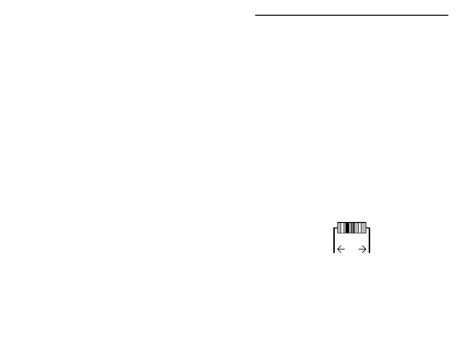
! ! 9. Locate R1, a 100K resistor (brown-black-yellow-gold). Carefully
bend the leads to form right-angles, install flush with the surface of the
PC board, and solder.
.4"
! ! 10. Locate R2, the one remaining resistor in your kit. R2 is 470-ohms
(yellow-violet-brown-gold). Install and solder.
! ! 11. Carefully recheck all your work to present. It will be easier to spot
and correct errors now, before L1 and Q1 are installed.
! ! 12. Locate L1, a slug-tuned coil shielded in a metal can (.074 uH, red coil
form). Note the two small solder tabs and wire coil leads. These must
be straight before you attempt to install the coil.
! ! 13. Install L1, making sure it is straight and seated flush to the PC board
(some coils may have shouldered tabs that limit insertion depth.) On