Figure 9, Table 11 – Zilog EZ80F91 User Manual
Page 31
Advertising
eZ80F91 Development Kit
User Manual
UM014220-0508
eZ80 Development Kit
26
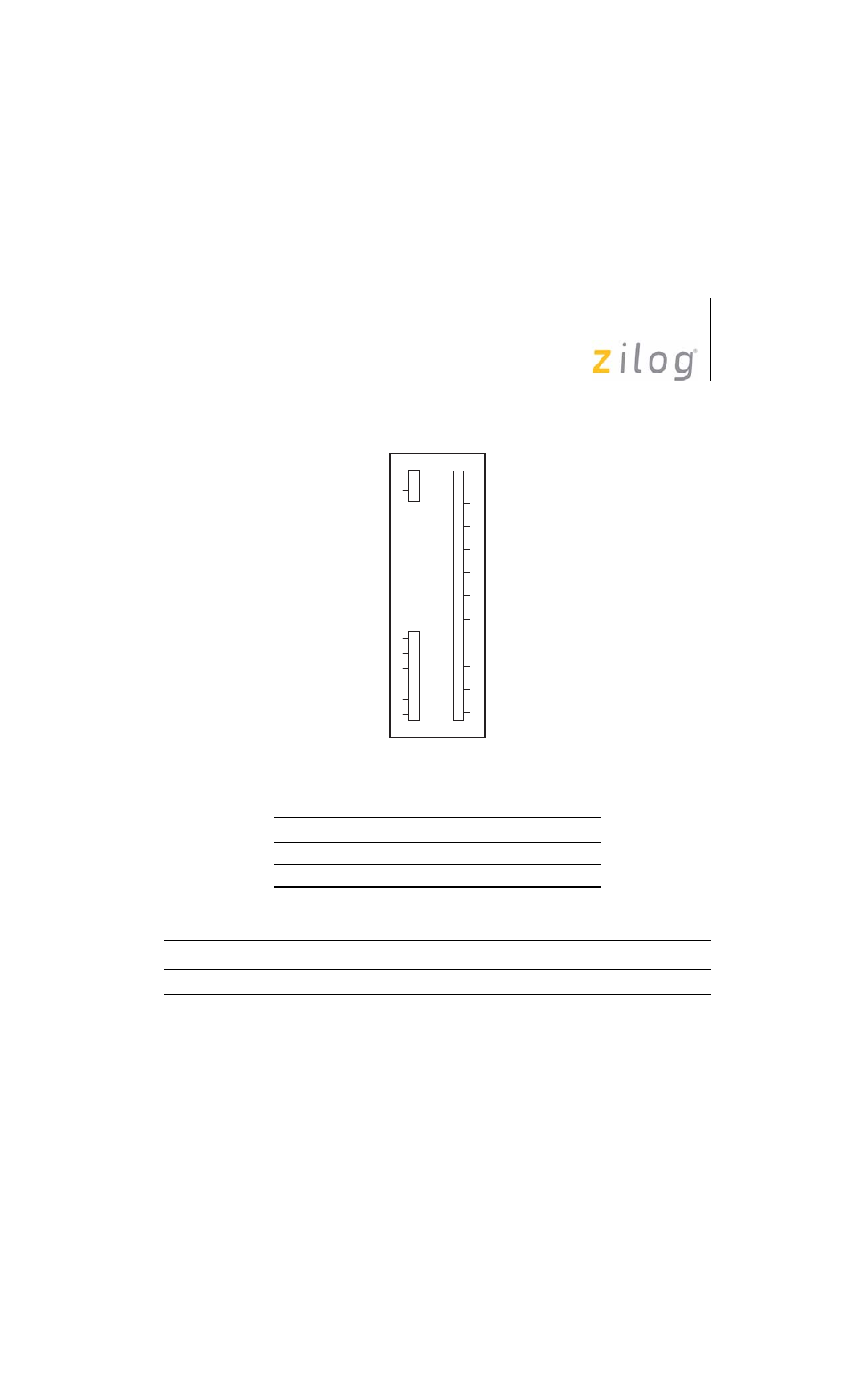
Figure 9. Embedded Modem Socket Interface—J1, J5, and J9
Table 11. Connector J5
Pin Symbol
Description
1
M-TIP
Telephone Line Interface—TIP
2
M-RING
Telephone Line Interface—RING
Table 12. Connector J9
Pin Symbol
Description
1
MRESET
Reset, active Low, 50–100 ms. Closure to GND for reset
3
GND
Ground
6
D1
DCD indicator; can drive an LED anode without additional circuitry
J5
J9
J1
1
2
4
24
25
26
27
28
29
30
31
32
2
1
3
6
7
8
9
Advertising
This manual is related to the following products: