Port a register diagrams – Zilog Z8PE002 User Manual
Page 35
Advertising
Z8PE002
ZiLOG
Z8Plus OTP Microcontroller
DS008700-Z8X0799
P R E L I M I N A R Y
35
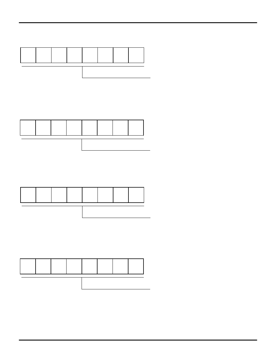
PORT A REGISTER DIAGRAMS
Figure 28. Port A Input Value Register
Figure 29. Port A Output Value Register
Figure 30. Port A Directional Control Register
Figure 31. Port A Special Function Register
D7
D6
D5
D4
D3
D2
D1
D0
Register 0D0H
PTAIN
Port A Bit n current input value
(only updated for pins in input mode)
D7
D6
D5
D4
D3
D2
D1
D0
Register 0D1H
PTAOUT
Port A Bit n currentoutput value
D7
D6
D5
D4
D3
D2
D1
D0
Register 0D2H
PTADIR
1 = Bit n set as an output
0 = Bit n set as an input
D7
D6
D5
D4
D3
D2
D1
D0
Register 0D3H
PTASFR
1 = Bit n in open-drain mode
0 = Bit n in push-pull mode
Advertising